How to Use USB HUB: Examples, Pinouts, and Specs
Introduction
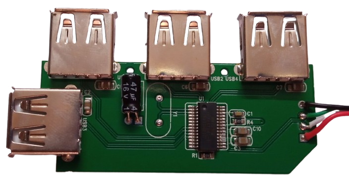
A USB Hub is an electronic device that expands a single USB port into several, allowing multiple USB devices to be connected to a computer. This component is essential for users who need to connect multiple peripherals, such as keyboards, mice, printers, and external storage devices, to a single USB port. USB Hubs are commonly used in both personal and professional settings to enhance connectivity and improve workflow efficiency.
Explore Projects Built with USB HUB


Explore Projects Built with USB HUB
Technical Specifications
Key Technical Details
| Specification | Value |
|---|---|
| USB Standard | USB 2.0 / USB 3.0 / USB 3.1 |
| Number of Ports | 4, 7, or more |
| Input Voltage | 5V DC |
| Output Voltage | 5V DC |
| Maximum Current | 500mA per port (USB 2.0) |
| 900mA per port (USB 3.0/3.1) | |
| Data Transfer Rate | Up to 480 Mbps (USB 2.0) |
| Up to 5 Gbps (USB 3.0) | |
| Up to 10 Gbps (USB 3.1) | |
| Power Supply | Bus-powered or Self-powered |
| Operating Temperature | 0°C to 70°C |
Pin Configuration and Descriptions
| Pin Number | Pin Name | Description |
|---|---|---|
| 1 | VBUS | +5V Power Supply |
| 2 | D- | Data Negative |
| 3 | D+ | Data Positive |
| 4 | GND | Ground |
Usage Instructions
How to Use the USB Hub in a Circuit
Connect the USB Hub to the Host Device:
- Plug the USB Hub's upstream port into the USB port of your computer or other host device.
Connect USB Devices to the Hub:
- Plug your USB peripherals (e.g., keyboard, mouse, printer) into the downstream ports of the USB Hub.
Power the Hub (if Self-Powered):
- If the USB Hub is self-powered, connect the external power adapter to the hub and plug it into a power outlet.
Important Considerations and Best Practices
Power Requirements:
- Ensure that the total current draw of all connected devices does not exceed the maximum current rating of the USB Hub.
- For high-power devices, use a self-powered USB Hub to provide sufficient power.
Data Transfer Rates:
- Use USB 3.0 or USB 3.1 Hubs for high-speed data transfer applications.
- Ensure that both the host device and the connected peripherals support the desired USB standard.
Cable Length:
- Keep USB cable lengths within recommended limits to avoid signal degradation and data transfer issues.
Troubleshooting and FAQs
Common Issues and Solutions
USB Devices Not Recognized:
- Solution: Ensure that the USB Hub is properly connected to the host device and that the hub is receiving power. Try connecting the USB devices directly to the host device to verify their functionality.
Slow Data Transfer Rates:
- Solution: Verify that both the USB Hub and the connected devices support the same USB standard (e.g., USB 3.0). Use high-quality USB cables and minimize cable length.
Overcurrent Warnings:
- Solution: Check the total current draw of all connected devices. If it exceeds the hub's maximum current rating, disconnect some devices or use a self-powered USB Hub.
FAQs
Q1: Can I connect a USB Hub to another USB Hub?
- A1: Yes, you can daisy-chain USB Hubs, but the total number of connected devices and the overall power requirements should be considered.
Q2: Will a USB 3.0 Hub work with USB 2.0 devices?
- A2: Yes, USB 3.0 Hubs are backward compatible with USB 2.0 devices, but the data transfer rate will be limited to USB 2.0 speeds.
Q3: Do I need a driver to use a USB Hub?
- A3: Most USB Hubs are plug-and-play and do not require additional drivers. However, some advanced hubs with special features may require drivers provided by the manufacturer.
Example Code for Arduino UNO
While USB Hubs are not typically interfaced directly with microcontrollers like the Arduino UNO, you can use the USB Host Shield to connect USB devices to the Arduino. Below is an example code to interface a USB keyboard with an Arduino UNO using the USB Host Shield.
#include <hidboot.h>
#include <usbhub.h>

USB     Usb;
HIDBoot<USB_HID_PROTOCOL_KEYBOARD>    Keyboard(&Usb);

class KbdRptParser : public KeyboardReportParser {
  void PrintKey(uint8_t mod, uint8_t key);
protected:
  void OnKeyDown(uint8_t mod, uint8_t key);
  void OnKeyPressed(uint8_t key);
};

KbdRptParser KbdPrs;

void setup() {
  Serial.begin(115200);
  if (Usb.Init() == -1) {
    Serial.println("OSC did not start.");
  }
  delay(200);
  Keyboard.SetReportParser(0, (HIDReportParser*)&KbdPrs);
}

void loop() {
  Usb.Task();
}

void KbdRptParser::OnKeyDown(uint8_t mod, uint8_t key) {
  uint8_t c = OemToAscii(mod, key);
  if (c) {
    OnKeyPressed(c);
  }
}

void KbdRptParser::OnKeyPressed(uint8_t key) {
  Serial.print("ASCII: ");
  Serial.println((char)key);
}
This code initializes the USB Host Shield and sets up a keyboard report parser to read key presses from a connected USB keyboard. The key presses are then printed to the Serial Monitor.
By following this documentation, users can effectively utilize a USB Hub in various applications, ensuring proper connectivity and performance.