
How to Use ACS712 30A Current Sensor Module: Examples, Pinouts, and Specs
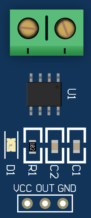
 Design with ACS712 30A Current Sensor Module in Cirkit Designer
Introduction
The ACS712 30A Current Sensor Module is a Hall effect-based sensor designed for precise current measurement in both AC and DC circuits. It can measure currents up to ±30A and outputs an analog voltage proportional to the current flowing through it. This module is widely used in applications such as motor control, power monitoring, battery management systems, and overcurrent protection.
Explore Projects Built with ACS712 30A Current Sensor Module
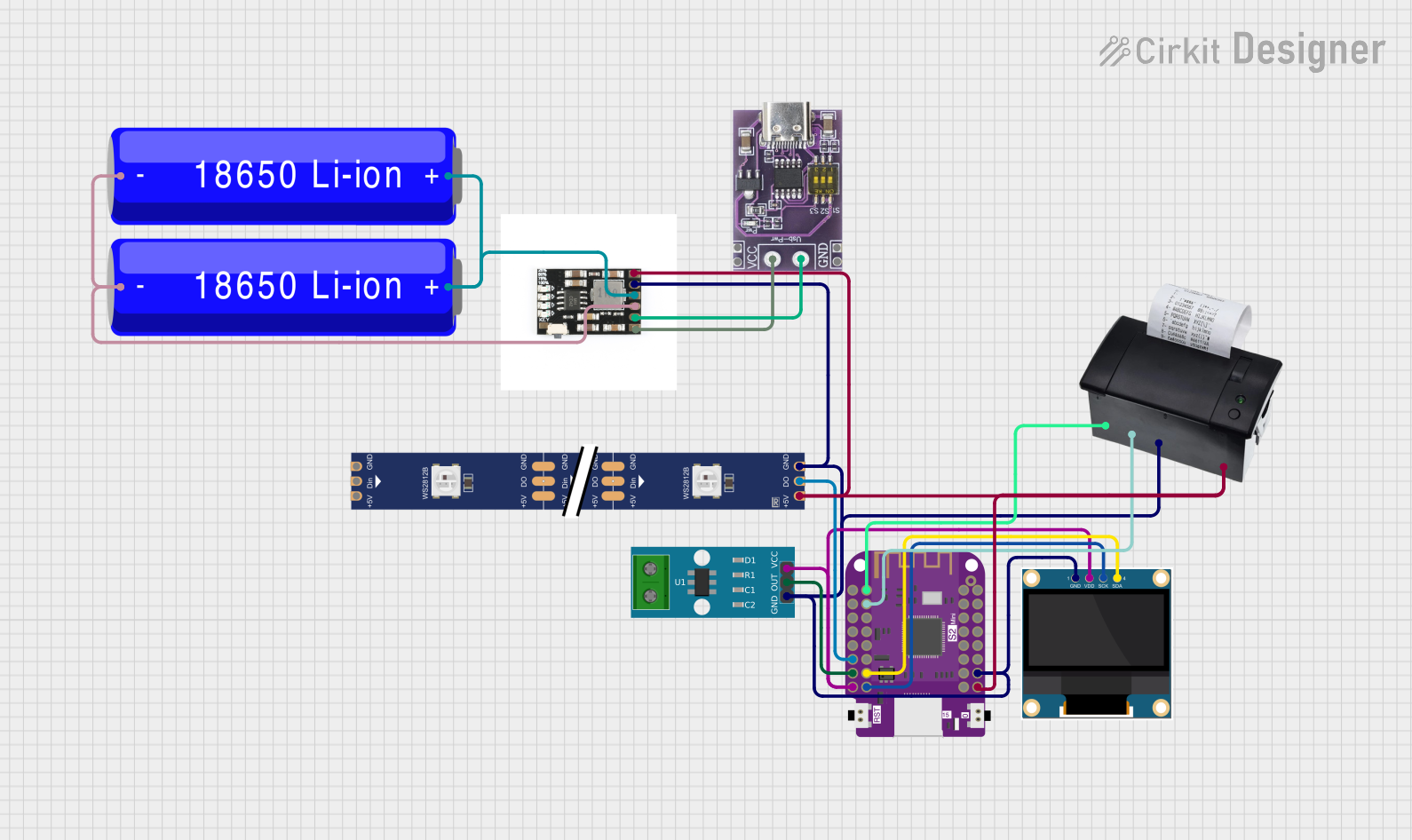 Open Project in Cirkit Designer
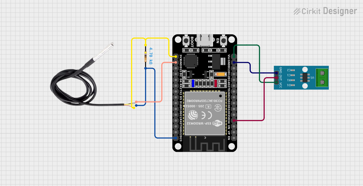 Open Project in Cirkit Designer
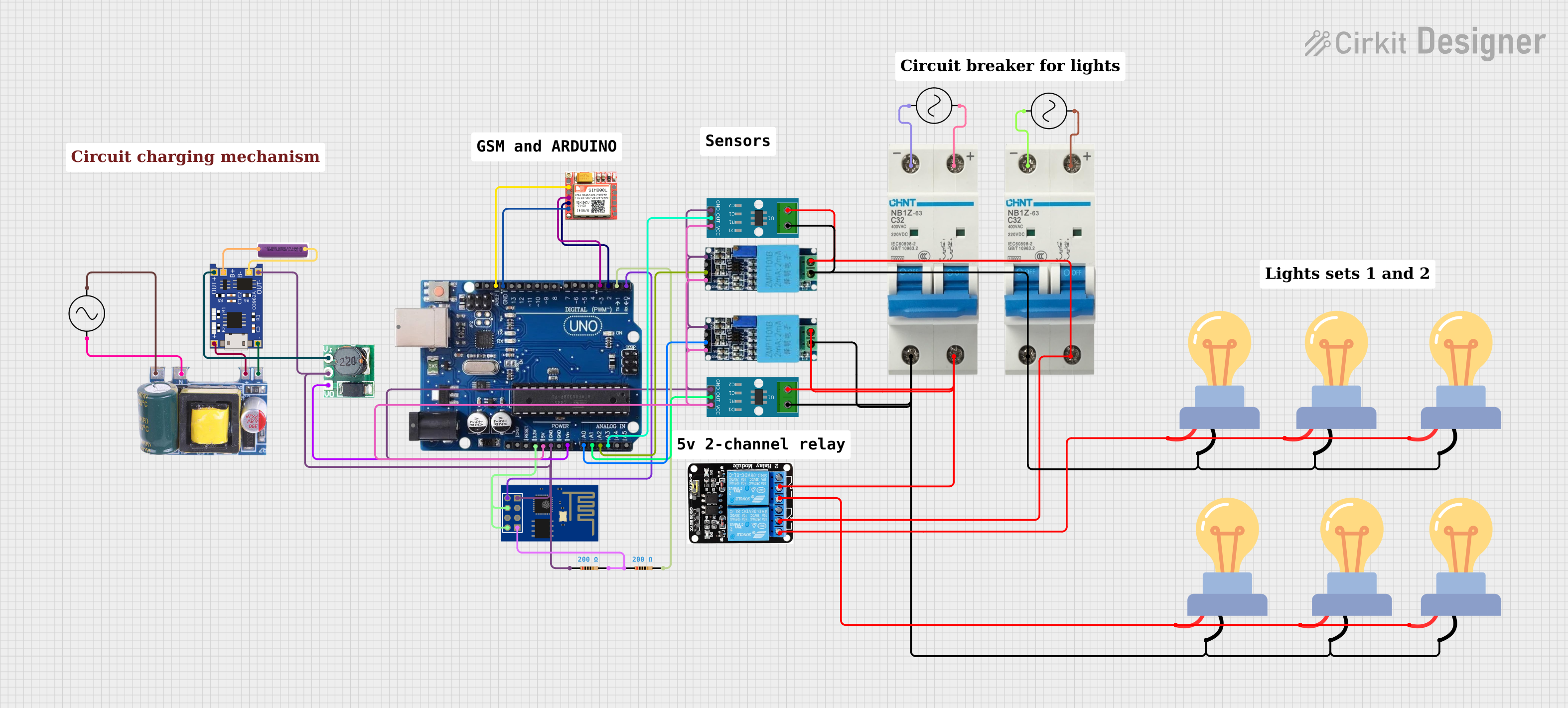 Open Project in Cirkit Designer
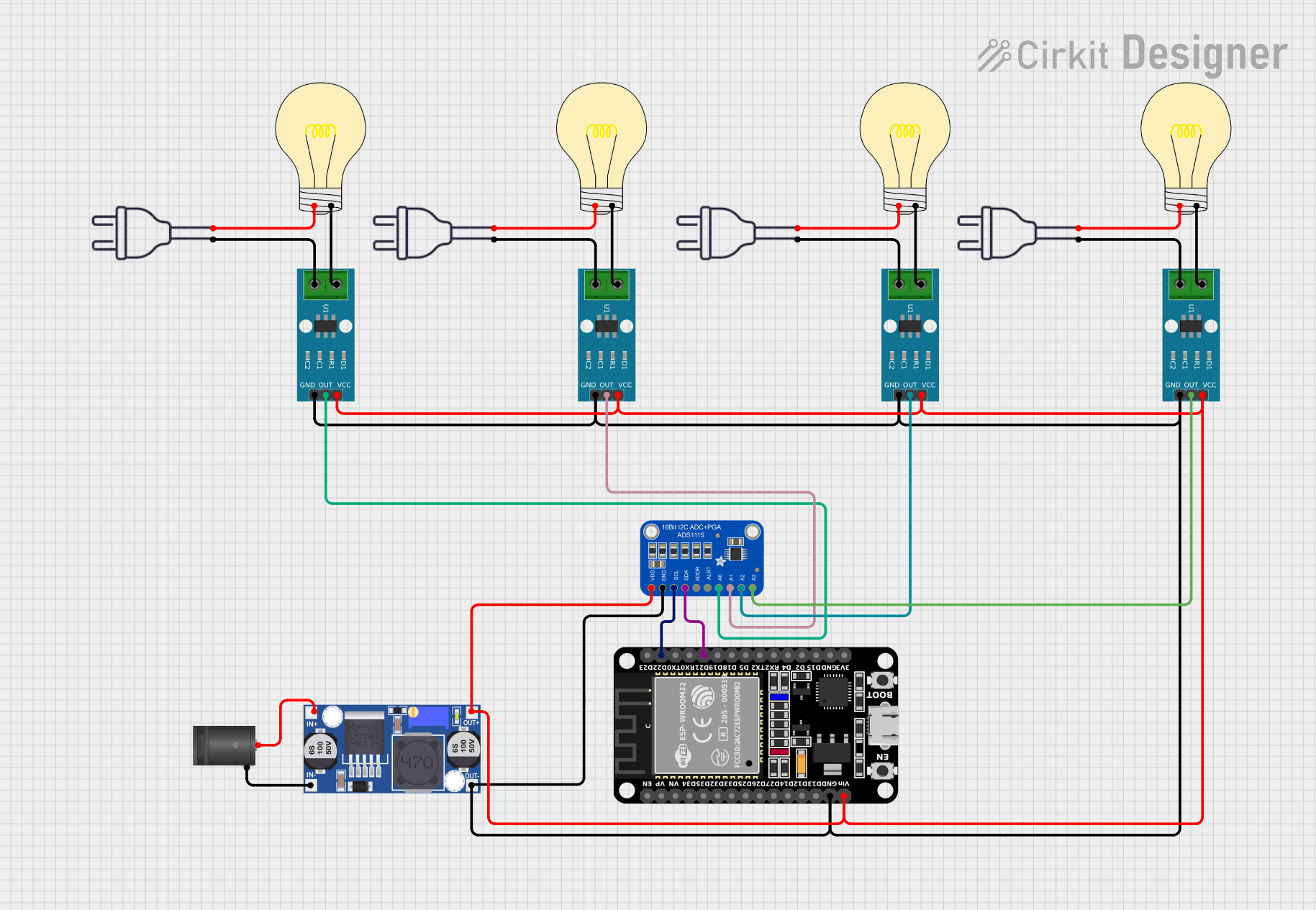 Open Project in Cirkit Designer
Explore Projects Built with ACS712 30A Current Sensor Module
Open Project in Cirkit DesignerOpen Project in Cirkit DesignerOpen Project in Cirkit DesignerOpen Project in Cirkit DesignerCommon Applications:
- Power consumption monitoring in appliances
- Overcurrent detection in motor drivers
- Battery charge and discharge monitoring
- Renewable energy systems (e.g., solar inverters)
- Industrial automation and control systems
Technical Specifications
Below are the key technical details of the ACS712 30A Current Sensor Module:
| Parameter | Value |
|---|---|
| Supply Voltage (Vcc) | 4.5V to 5.5V |
| Current Measurement Range | ±30A |
| Sensitivity | 66mV/A |
| Output Voltage Range | 0V to Vcc |
| Zero Current Output | ~2.5V (at Vcc = 5V) |
| Response Time | 5 µs |
| Accuracy | ±1.5% |
| Operating Temperature | -40°C to 85°C |
| Dimensions | 31mm x 13mm x 15mm |
Pin Configuration and Descriptions
The ACS712 module has three pins for interfacing and two terminals for current input/output:
| Pin | Name | Description |
|---|---|---|
| 1 | Vcc | Power supply input (4.5V to 5.5V). Typically connected to 5V from a microcontroller. |
| 2 | Out | Analog voltage output proportional to the measured current. |
| 3 | GND | Ground connection. |
| Terminal | Name | Description |
|---|---|---|
| 1 | IP+ (Input+) | Connect to the positive side of the current-carrying wire. |
| 2 | IP- (Input-) | Connect to the negative side of the current-carrying wire. |
Usage Instructions
How to Use the ACS712 in a Circuit
- Power the Module: Connect the
Vccpin to a 5V power supply and theGNDpin to the ground of your circuit. - Connect the Current Path: Pass the wire carrying the current to be measured through the
IP+andIP-terminals. Ensure the current does not exceed ±30A. - Read the Output: The
Outpin provides an analog voltage proportional to the current. At 0A, the output voltage is approximately 2.5V. For positive currents, the voltage increases, and for negative currents, it decreases.
Important Considerations:
- Calibration: The sensor's output may vary slightly due to manufacturing tolerances. Calibrate the sensor in your application for accurate results.
- Noise Filtering: Add a capacitor (e.g., 0.1µF) between the
Outpin andGNDto reduce noise in the output signal. - Current Direction: The module can measure both positive and negative currents. Ensure the current direction matches your application's requirements.
- Safety: Avoid exceeding the ±30A limit to prevent damage to the sensor.
Example: Using ACS712 with Arduino UNO
Below is an example code to measure current using the ACS712 module and an Arduino UNO:
// Include necessary libraries
const int sensorPin = A0; // Connect the 'Out' pin of ACS712 to Arduino A0
const float sensitivity = 0.066; // Sensitivity for ACS712 30A module (66mV/A)
const float zeroCurrentVoltage = 2.5; // Voltage at 0A (approximately 2.5V)

void setup() {
  Serial.begin(9600); // Initialize serial communication
  pinMode(sensorPin, INPUT); // Set the sensor pin as input
}

void loop() {
  int sensorValue = analogRead(sensorPin); // Read the analog value from the sensor
  float voltage = (sensorValue / 1023.0) * 5.0; // Convert ADC value to voltage
  float current = (voltage - zeroCurrentVoltage) / sensitivity;
  // Calculate current in Amperes

  Serial.print("Current: ");
  Serial.print(current, 2); // Print current with 2 decimal places
  Serial.println(" A"); // Append unit

  delay(1000); // Wait for 1 second before the next reading
}
Notes:
- Ensure the
zeroCurrentVoltagematches the actual output voltage of your sensor at 0A. - Use a stable 5V power supply for accurate readings.
Troubleshooting and FAQs
Common Issues and Solutions
No Output or Incorrect Readings:
- Verify that the
VccandGNDpins are properly connected to a 5V power supply and ground. - Check the wiring of the current-carrying wire through the
IP+andIP-terminals.
- Verify that the
High Noise in Output:
- Add a decoupling capacitor (e.g., 0.1µF) between the
Outpin andGND. - Ensure the sensor is not placed near high-frequency noise sources.
- Add a decoupling capacitor (e.g., 0.1µF) between the
Output Voltage Does Not Match Expected Values:
- Calibrate the sensor by measuring the output voltage at known current values and adjusting the sensitivity in your calculations.
- Ensure the current does not exceed the ±30A range.
Sensor Overheating:
- Ensure the current through the sensor does not exceed its rated capacity of ±30A.
- Check for proper ventilation around the module.
FAQs
Q1: Can the ACS712 measure both AC and DC currents?
Yes, the ACS712 can measure both AC and DC currents. The output voltage will vary proportionally with the instantaneous current.
Q2: What happens if the current exceeds 30A?
Exceeding the ±30A limit may damage the sensor or cause inaccurate readings. Use a higher-rated sensor for larger currents.
Q3: How do I improve measurement accuracy?
Calibrate the sensor in your specific application, use a stable power supply, and add noise filtering capacitors.
Q4: Can I use the ACS712 with a 3.3V microcontroller?
Yes, but the output voltage range will be limited. Ensure the microcontroller's ADC can accurately read the sensor's output within this range.
Q5: Is the ACS712 isolated from the current-carrying wire?
Yes, the Hall effect-based design provides electrical isolation between the current path and the sensor's output.