
How to Use DIN7: Examples, Pinouts, and Specs
 Design with DIN7 in Cirkit Designer
Introduction
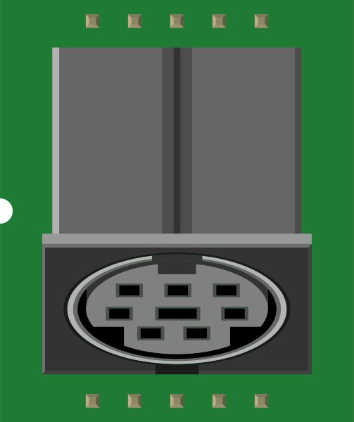
The DIN7 connector is a 7-pin DIN (Deutsches Institut für Normung) connector commonly used for audio, video, and data connections. It provides a reliable and durable interface for connecting various electronic devices. The circular design and standardized pin layout make it a versatile choice for both consumer and industrial applications.
Explore Projects Built with DIN7
 Open Project in Cirkit Designer
 Open Project in Cirkit Designer
 Open Project in Cirkit Designer
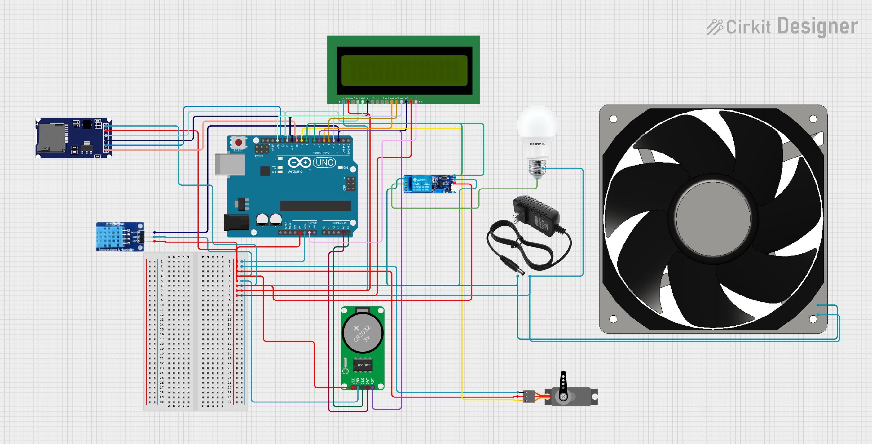 Open Project in Cirkit Designer
Explore Projects Built with DIN7
Open Project in Cirkit DesignerOpen Project in Cirkit DesignerOpen Project in Cirkit DesignerOpen Project in Cirkit DesignerCommon Applications and Use Cases
- Audio equipment connections (e.g., MIDI devices, amplifiers, and mixers)
- Video signal transmission
- Data communication in industrial systems
- Legacy computer peripherals
- Robotics and automation systems
Technical Specifications
Key Technical Details
- Connector Type: 7-pin DIN (circular)
- Number of Pins: 7
- Pin Spacing: 1.27 mm (standard DIN spacing)
- Voltage Rating: Up to 34V DC
- Current Rating: Up to 2A per pin
- Contact Resistance: ≤ 30 mΩ
- Insulation Resistance: ≥ 1000 MΩ at 500V DC
- Operating Temperature: -25°C to +70°C
- Material:
- Contacts: Gold-plated or nickel-plated brass
- Housing: Thermoplastic or metal (varies by model)
- Mounting Style: Panel mount or cable mount
Pin Configuration and Descriptions
The 7-pin DIN connector has a circular arrangement of pins. Below is the pinout configuration:
| Pin Number | Description | Common Use |
|---|---|---|
| 1 | Signal Ground | Ground connection |
| 2 | Audio Left Channel | Left audio signal |
| 3 | Audio Right Channel | Right audio signal |
| 4 | Data Signal 1 | Data communication |
| 5 | Data Signal 2 | Data communication |
| 6 | Power Supply (+V) | Positive voltage supply |
| 7 | Power Supply (-V or Ground) | Negative voltage or ground |
Note: The exact pin assignments may vary depending on the specific application or manufacturer. Always refer to the device's datasheet or manual for precise details.
Usage Instructions
How to Use the DIN7 Connector in a Circuit
- Identify the Pinout: Refer to the pin configuration table above to understand the function of each pin.
- Soldering:
- For cable-mounted connectors, solder the wires to the appropriate pins.
- Use heat shrink tubing to insulate the connections and prevent short circuits.
- Panel Mounting: If using a panel-mount connector, secure it to the panel using the provided nut or screws.
- Connection: Plug the male connector into the female socket, ensuring proper alignment to avoid bending the pins.
- Testing: Verify the connections using a multimeter to ensure continuity and correct wiring.
Important Considerations and Best Practices
- Alignment: Always align the connector properly before inserting it to avoid damaging the pins.
- Current and Voltage Limits: Do not exceed the specified voltage and current ratings to prevent overheating or damage.
- Shielding: Use shielded cables for audio and data applications to minimize interference.
- Environmental Conditions: Ensure the connector is used within its operating temperature range and protected from moisture if not rated for outdoor use.
Example: Connecting a DIN7 to an Arduino UNO
The DIN7 connector can be used to interface with an Arduino UNO for data communication. Below is an example of how to connect and program the Arduino to read data from a device using the DIN7 connector.
Wiring Diagram
- DIN7 Pin 4: Connect to Arduino Digital Pin 2 (Data Input)
- DIN7 Pin 5: Connect to Arduino Digital Pin 3 (Data Output)
- DIN7 Pin 6: Connect to Arduino 5V
- DIN7 Pin 7: Connect to Arduino GND
Arduino Code Example
// Example code to read data from a device using a DIN7 connector
// Pin 4 (Data Input) is connected to Arduino Digital Pin 2
// Pin 5 (Data Output) is connected to Arduino Digital Pin 3

const int dataInputPin = 2;  // Define the data input pin
const int dataOutputPin = 3; // Define the data output pin

void setup() {
  pinMode(dataInputPin, INPUT);  // Set data input pin as input
  pinMode(dataOutputPin, OUTPUT); // Set data output pin as output
  Serial.begin(9600); // Initialize serial communication at 9600 baud
}

void loop() {
  int inputData = digitalRead(dataInputPin); // Read data from the input pin
  Serial.print("Received Data: ");
  Serial.println(inputData); // Print the received data to the Serial Monitor

  // Example: Send a signal back through the output pin
  digitalWrite(dataOutputPin, HIGH); // Set output pin HIGH
  delay(100); // Wait for 100ms
  digitalWrite(dataOutputPin, LOW); // Set output pin LOW
  delay(100); // Wait for 100ms
}
Note: Ensure the connected device is compatible with the Arduino's voltage levels (5V logic).
Troubleshooting and FAQs
Common Issues Users Might Face
Loose Connections:
- Problem: The connector feels loose or the connection is intermittent.
- Solution: Ensure the connector is properly aligned and securely plugged in. Check for bent or damaged pins.
Signal Interference:
- Problem: Noise or distortion in audio or data signals.
- Solution: Use shielded cables and ensure proper grounding.
Overheating:
- Problem: The connector or cable becomes hot during operation.
- Solution: Verify that the current and voltage ratings are not being exceeded.
Incorrect Pinout:
- Problem: The device does not function as expected.
- Solution: Double-check the pin configuration and wiring. Refer to the device's datasheet for the correct pinout.
Solutions and Tips for Troubleshooting
- Use a multimeter to test continuity and verify connections.
- Inspect the connector for physical damage, such as bent pins or cracked housing.
- If using the connector in a high-vibration environment, consider securing the connection with a locking mechanism or adhesive.
By following this documentation, users can effectively integrate the DIN7 connector into their projects and troubleshoot common issues with ease.