How to Use 12V LED BUZZER: Examples, Pinouts, and Specs
12V LED Buzzer Documentation
Manufacturer: AC
Part ID: LED BUZZER
1. Introduction
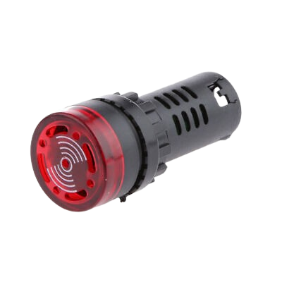
The 12V LED Buzzer is a compact and versatile electronic component designed for sound alerts and visual notifications. It combines an audible buzzer with an integrated LED that lights up when the buzzer is activated, making it ideal for applications requiring both sound and light indicators. This component is widely used in alarm systems, industrial equipment, home automation, and DIY electronics projects.
Common Applications:
- Security systems (e.g., door alarms, motion detectors)
- Notification systems in industrial machinery
- Home automation (e.g., smart doorbells, alerts)
- Arduino and microcontroller-based projects
- DIY electronics for sound and light signaling
2. Technical Specifications
The following table outlines the key technical details of the 12V LED Buzzer:
| Parameter | Value |
|---|---|
| Operating Voltage | 12V DC |
| Operating Current | 15-30 mA |
| Sound Output | 85-95 dB (at 10 cm distance) |
| Frequency Range | 2-4 kHz |
| LED Color | Red |
| Dimensions | 30mm (diameter) x 20mm (height) |
| Operating Temperature | -20°C to +60°C |
Pin Configuration
The 12V LED Buzzer has two pins for connection:
| Pin | Description |
|---|---|
| VCC | Positive terminal (+12V) |
| GND | Ground terminal (0V) |
3. Usage Instructions
Connecting the 12V LED Buzzer to a Circuit
Power Supply:
- Connect the VCC pin of the buzzer to a 12V DC power source.
- Connect the GND pin to the ground of the power source.
Control with a Microcontroller (e.g., Arduino):
- Use a digital output pin from the microcontroller to control the buzzer.
- A current-limiting resistor (e.g., 220Ω) may be added in series with the VCC pin for protection.
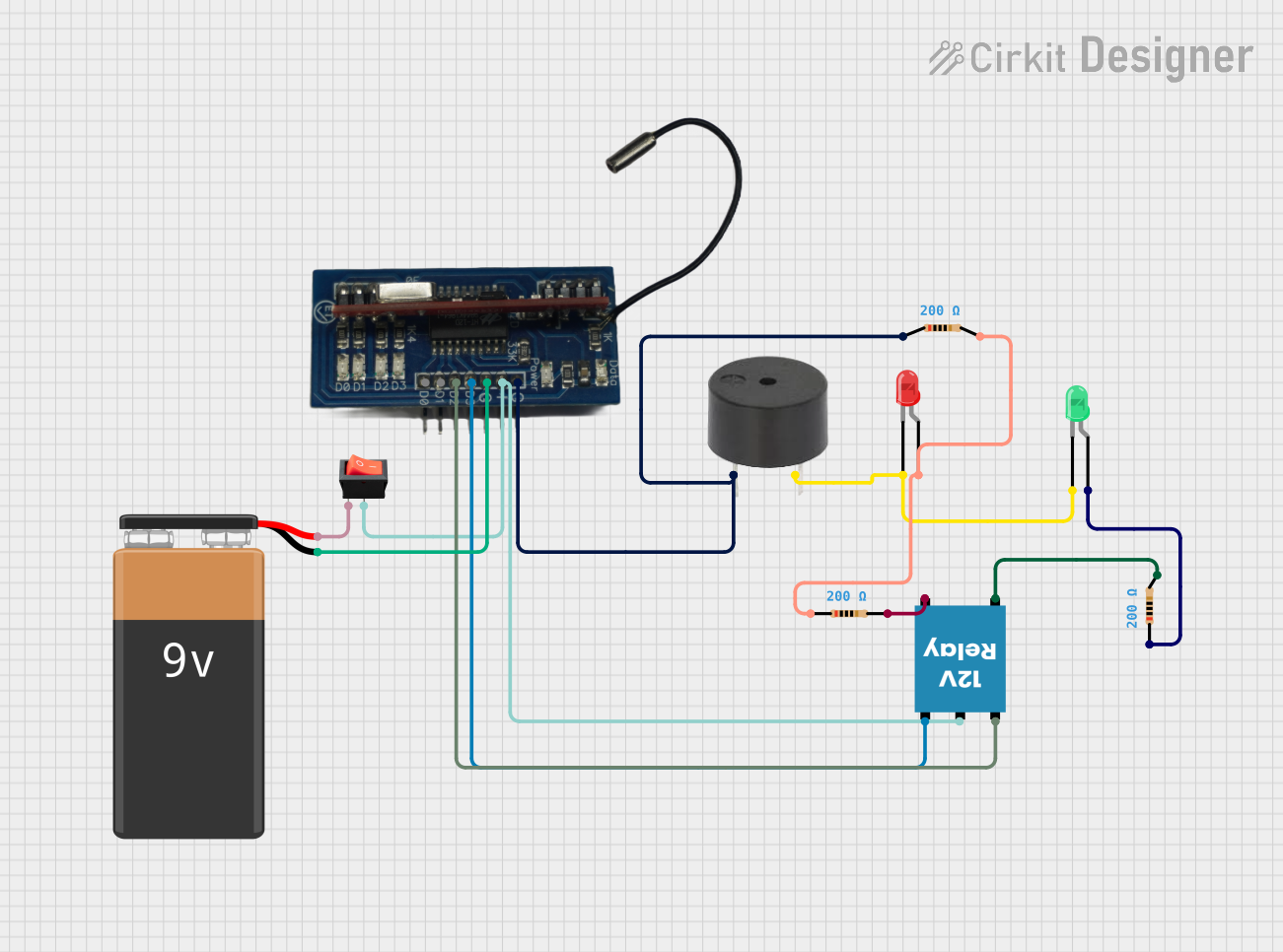
Example Circuit Diagram:
+12V DC ----> VCC (Buzzer)
              |
              R (Optional Resistor)
              |
GND ---------> GND (Buzzer)
Important Considerations:
- Ensure the power supply voltage does not exceed 12V to avoid damaging the component.
- Avoid prolonged activation of the buzzer in high-temperature environments.
- If using with a microcontroller, ensure the output pin can handle the required current (15-30 mA).
4. Arduino Example Code
Below is an example of how to use the 12V LED Buzzer with an Arduino UNO. The buzzer will turn on for 1 second and off for 1 second in a loop.
// Define the pin connected to the buzzer
const int buzzerPin = 8; // Connect the VCC pin of the buzzer to pin 8

void setup() {
  pinMode(buzzerPin, OUTPUT); // Set the buzzer pin as an output
}

void loop() {
  digitalWrite(buzzerPin, HIGH); // Turn the buzzer ON
  delay(1000);                   // Wait for 1 second
  digitalWrite(buzzerPin, LOW);  // Turn the buzzer OFF
  delay(1000);                   // Wait for 1 second
}
Notes:
- Connect the VCC pin of the buzzer to pin 8 of the Arduino.
- Connect the GND pin of the buzzer to the Arduino's GND.
- If the buzzer does not activate, check the connections and ensure the Arduino is powered.
5. Troubleshooting and FAQs
Common Issues and Solutions
| Issue | Possible Cause | Solution |
|---|---|---|
| Buzzer does not activate | Incorrect wiring or loose connections | Verify VCC and GND connections. |
| LED lights up, but no sound | Insufficient voltage or current | Ensure a stable 12V DC power supply. |
| Buzzer is too quiet | Distance from the buzzer is too large | Place the buzzer closer to the listener. |
| Buzzer overheats | Prolonged activation or overvoltage | Limit activation time and check voltage. |
Frequently Asked Questions
Can I use the buzzer with a 5V power supply?
- No, the buzzer is designed for 12V operation. Using 5V may result in insufficient sound output or failure to activate.
Do I need a resistor when connecting the buzzer to an Arduino?
- A resistor is optional but recommended for current limiting, especially if the Arduino pin cannot handle the required current.
Can I control the buzzer with a transistor?
- Yes, you can use an NPN transistor (e.g., 2N2222) to control the buzzer if the microcontroller cannot supply enough current.
Is the buzzer polarity-sensitive?
- Yes, ensure the VCC pin is connected to the positive terminal and the GND pin to the ground. Reversing the polarity may damage the component.
6. Conclusion
The 12V LED Buzzer is a reliable and easy-to-use component for sound and light notifications. Its simple design and compatibility with microcontrollers like Arduino make it a popular choice for a wide range of applications. By following the guidelines in this documentation, users can integrate the buzzer into their projects with ease and confidence.
For further assistance, refer to the manufacturer's datasheet or contact technical support.
Explore Projects Built with 12V LED BUZZER
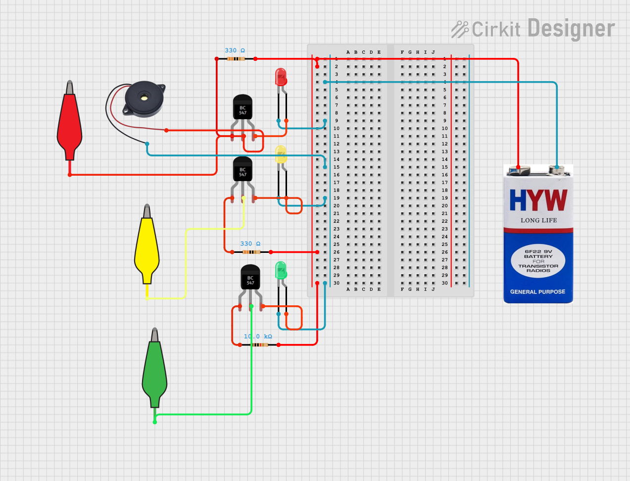
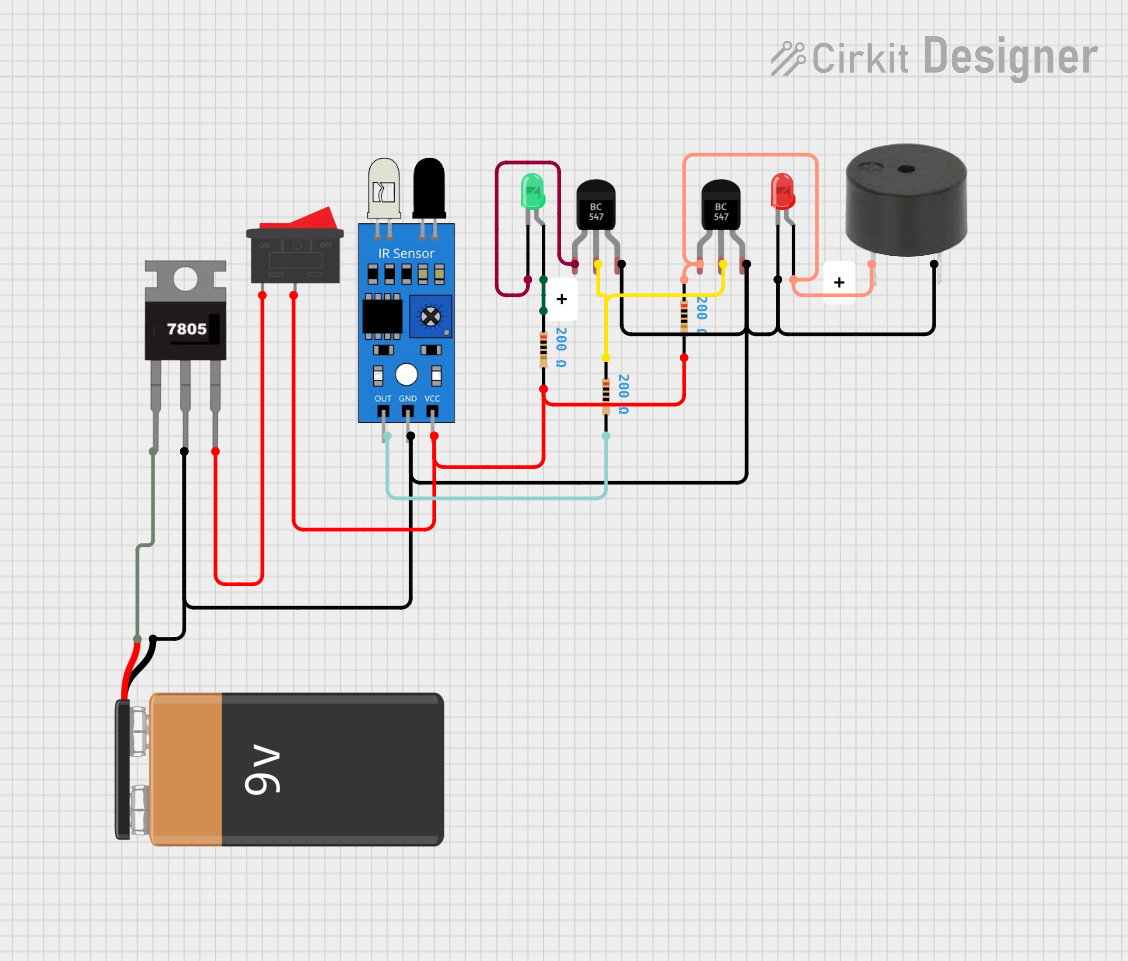
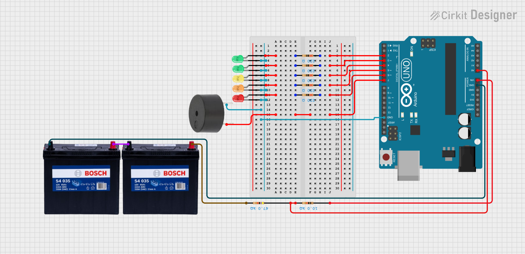
Explore Projects Built with 12V LED BUZZER