
How to Use Wiring Mini: Examples, Pinouts, and Specs
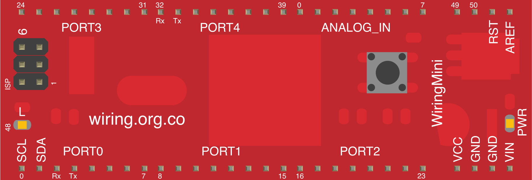
 Design with Wiring Mini in Cirkit Designer
Introduction
Wiring Mini refers to small gauge wires designed for connecting components in electronic circuits. These wires are compact, flexible, and efficient, making them ideal for use in tight spaces or intricate circuit designs. They are commonly used in prototyping, breadboarding, and permanent installations where space-saving and reliable connections are essential.
Explore Projects Built with Wiring Mini
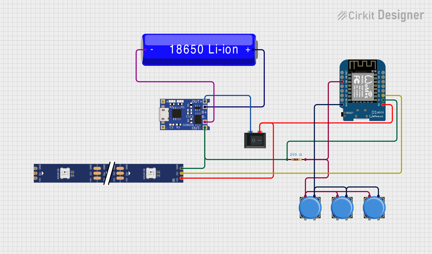 Open Project in Cirkit Designer
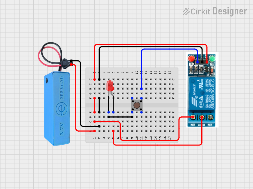 Open Project in Cirkit Designer
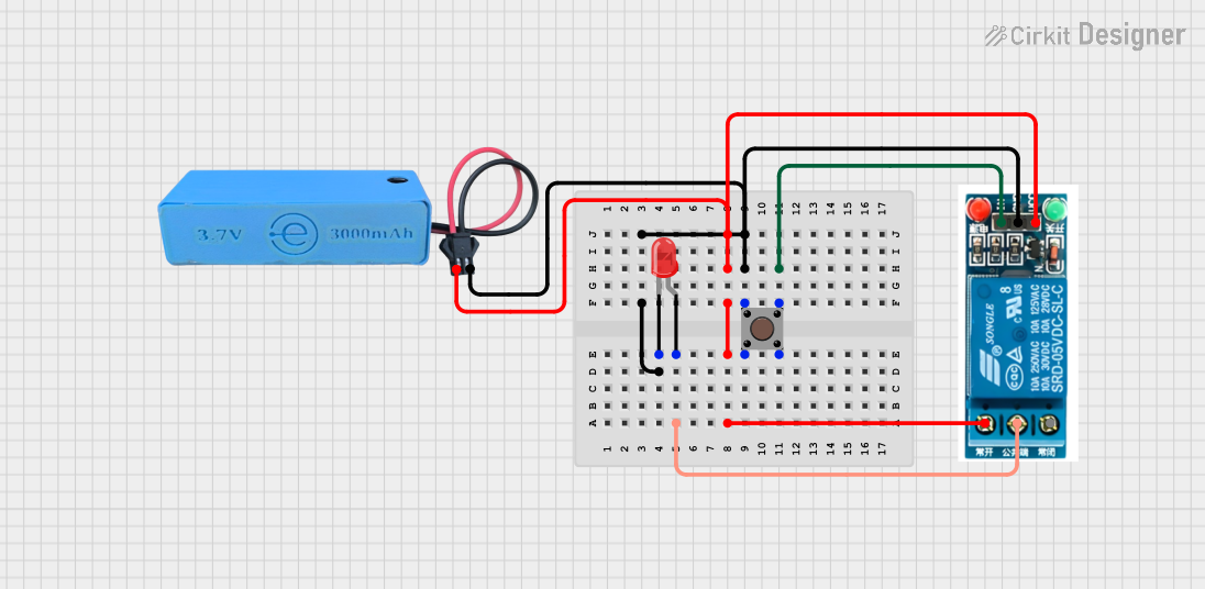 Open Project in Cirkit Designer
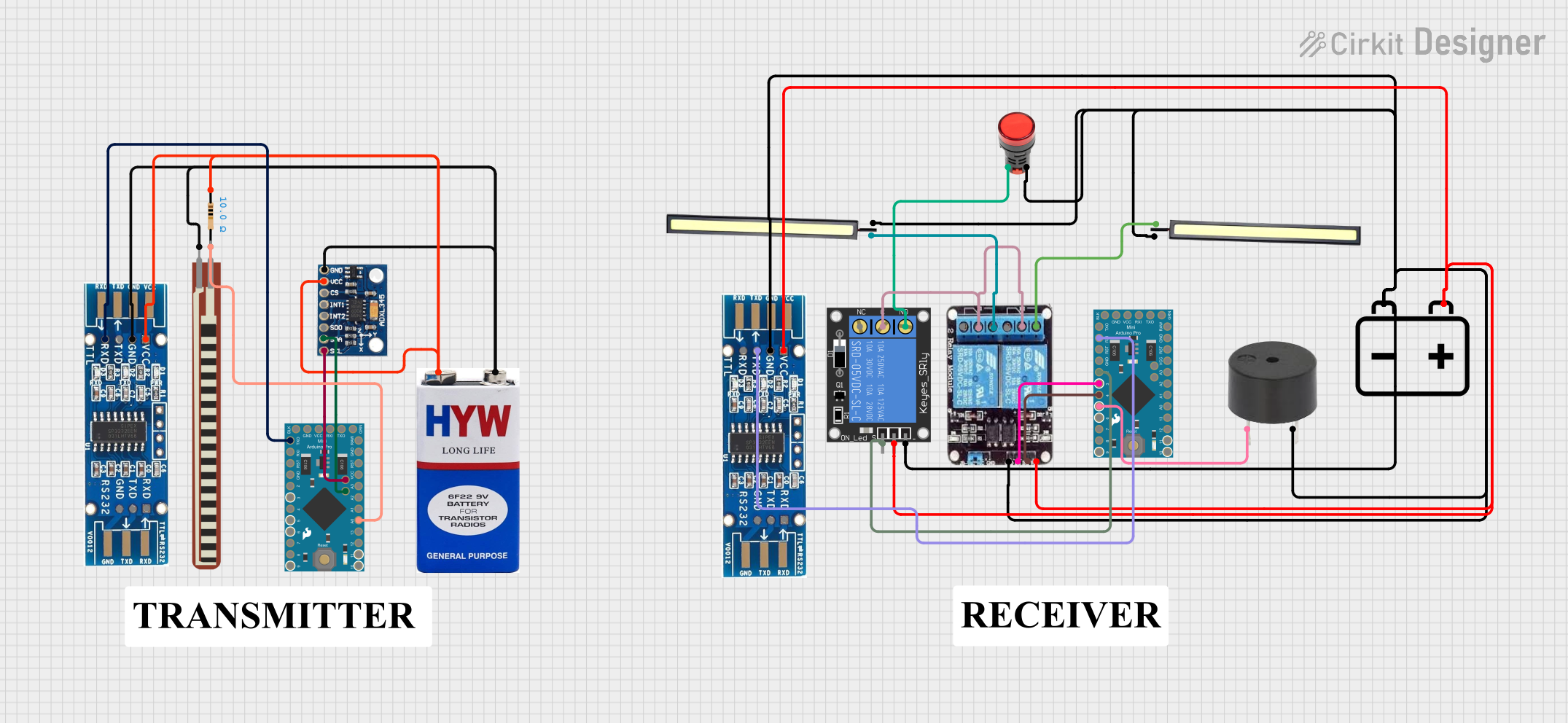 Open Project in Cirkit Designer
Explore Projects Built with Wiring Mini
Open Project in Cirkit DesignerOpen Project in Cirkit DesignerOpen Project in Cirkit DesignerOpen Project in Cirkit DesignerCommon Applications and Use Cases
- Prototyping and breadboard connections
- Internal wiring for compact electronic devices
- Signal and low-power connections in circuits
- Robotics and IoT projects requiring lightweight wiring
- Arduino and microcontroller-based projects
Technical Specifications
Wiring Mini is available in various specifications depending on the application. Below are the general technical details:
Key Technical Details
| Parameter | Specification |
|---|---|
| Wire Gauge (AWG) | 22 to 30 AWG |
| Insulation Material | PVC, Silicone, or Teflon |
| Voltage Rating | Typically 300V |
| Current Rating | 0.5A to 3A (depending on gauge) |
| Temperature Range | -60°C to 200°C (varies by insulation) |
| Conductor Material | Stranded or solid copper |
| Length Options | Pre-cut lengths or spools (varies) |
Pin Configuration and Descriptions
Wiring Mini does not have pins but is typically terminated with connectors or soldered directly to components. Below are common termination methods:
| Termination Type | Description |
|---|---|
| Bare Wire Ends | Stripped ends for direct soldering |
| Crimped Connectors | Used with terminals or headers |
| Dupont Connectors | Common for breadboards and Arduino |
| Pre-tinned Ends | Easier soldering to PCB pads |
Usage Instructions
How to Use Wiring Mini in a Circuit
- Select the Appropriate Gauge: Choose the wire gauge based on the current and voltage requirements of your circuit. For low-power signals, 28-30 AWG is sufficient, while 22-24 AWG is better for higher currents.
- Cut to Length: Measure and cut the wire to the required length using wire cutters.
- Strip the Insulation: Use a wire stripper to remove about 5-10mm of insulation from each end of the wire.
- Terminate the Ends:
- For soldering, pre-tin the stripped ends with solder.
- For connectors, crimp or attach the appropriate connector to the wire ends.
- Connect to Components: Attach the wire to the circuit components, ensuring secure and reliable connections.
- Secure the Wiring: Use cable ties or adhesive mounts to organize and secure the wires in place.
Important Considerations and Best Practices
- Avoid Overloading: Ensure the wire gauge matches the current requirements to prevent overheating.
- Use Heat Shrink Tubing: For added insulation and durability, cover soldered joints with heat shrink tubing.
- Minimize Signal Interference: For signal wires, keep them short and away from high-power lines to reduce noise.
- Test Connections: Use a multimeter to verify continuity and proper connections before powering the circuit.
Example: Connecting Wiring Mini to an Arduino UNO
Below is an example of using Wiring Mini to connect an LED to an Arduino UNO:
// Example: Blink an LED using Wiring Mini with Arduino UNO
// Connect one end of the Wiring Mini to pin 13 on the Arduino
// and the other end to the positive leg of the LED. Use a 220-ohm
// resistor in series with the LED to limit current.

int ledPin = 13; // Pin connected to the LED

void setup() {
  pinMode(ledPin, OUTPUT); // Set pin 13 as an output
}

void loop() {
  digitalWrite(ledPin, HIGH); // Turn the LED on
  delay(1000);               // Wait for 1 second
  digitalWrite(ledPin, LOW);  // Turn the LED off
  delay(1000);               // Wait for 1 second
}
Troubleshooting and FAQs
Common Issues Users Might Face
- Loose Connections: Wires may come loose from breadboards or connectors.
- Solution: Ensure wires are securely inserted or crimped. Use Dupont connectors for breadboards.
- Overheating Wires: Using an incorrect gauge for high-current applications can cause overheating.
- Solution: Select a thicker wire (lower AWG) for higher current loads.
- Signal Interference: Long wires or proximity to high-power lines can introduce noise.
- Solution: Use shorter wires and route signal wires away from power lines.
- Frayed Ends: Stranded wires may fray when stripped.
- Solution: Twist the strands together or use pre-tinned wires.
FAQs
Q: Can Wiring Mini handle high-power applications?
A: Wiring Mini is best suited for low-power and signal connections. For high-power applications, use thicker wires with higher current ratings.
Q: What is the difference between stranded and solid wire?
A: Stranded wire is more flexible and suitable for dynamic applications, while solid wire is rigid and better for fixed installations.
Q: How do I prevent wires from tangling in my project?
A: Use cable ties, wire looms, or adhesive mounts to organize and secure the wires neatly.
Q: Can I use Wiring Mini outdoors?
A: Only if the insulation material is rated for outdoor use (e.g., Teflon or weather-resistant PVC).