How to Use ESP32C3 Dev: Examples, Pinouts, and Specs
Introduction
The ESP32C3 Dev is a compact and versatile development board built around the ESP32-C3 chip, manufactured by ESP32. This board integrates Wi-Fi and Bluetooth Low Energy (BLE) capabilities, making it an excellent choice for IoT (Internet of Things) applications. It is designed to simplify prototyping and development of connected devices, offering a rich set of GPIO pins, ADCs, and support for multiple communication protocols.
Explore Projects Built with ESP32C3 Dev


Explore Projects Built with ESP32C3 Dev
Common Applications and Use Cases
- Smart home devices (e.g., connected lights, thermostats)
- Wearable technology
- Industrial IoT sensors and controllers
- Wireless data logging and monitoring
- BLE-based proximity and beacon applications
- Educational and hobbyist projects
Technical Specifications
The ESP32C3 Dev board is equipped with the ESP32-C3 chip, which is based on the RISC-V architecture. Below are the key technical details:
Key Specifications
| Parameter | Value |
|---|---|
| Microcontroller | ESP32-C3 (RISC-V single-core processor) |
| Clock Speed | Up to 160 MHz |
| Flash Memory | 4 MB (varies by board version) |
| SRAM | 400 KB |
| Wi-Fi Standard | 802.11 b/g/n (2.4 GHz) |
| Bluetooth | BLE 5.0 |
| Operating Voltage | 3.3 V |
| GPIO Pins | 22 (multiplexed with other functions) |
| ADC Channels | 6 (12-bit resolution) |
| Communication Interfaces | UART, SPI, I2C, I2S, PWM |
| USB Interface | USB Type-C (for programming and power) |
| Power Supply | 5 V (via USB) or 3.3 V (via pin) |
| Dimensions | ~52 mm x 25 mm |
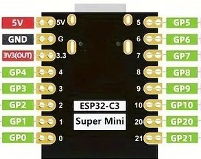
Pin Configuration and Descriptions
The ESP32C3 Dev board features a variety of pins for different functionalities. Below is the pinout description:
| Pin Name | Functionality | Description |
|---|---|---|
| 3V3 | Power | 3.3 V output for powering external components |
| GND | Ground | Common ground |
| GPIO0 | Digital I/O, Boot Mode Selection | Used for programming and general I/O |
| GPIO1 | Digital I/O, UART TX | UART transmit pin |
| GPIO2 | Digital I/O, ADC | General-purpose I/O or ADC input |
| GPIO3 | Digital I/O, UART RX | UART receive pin |
| GPIO4 | Digital I/O, PWM | General-purpose I/O or PWM output |
| GPIO5 | Digital I/O, ADC | General-purpose I/O or ADC input |
| GPIO6-21 | Digital I/O, ADC, SPI, I2C, PWM | Multiplexed pins for various functions |
| EN | Enable | Resets the board when pulled low |
| USB | USB Type-C | Used for programming and power supply |
Note: Some GPIO pins have specific restrictions or dual functionalities. Refer to the ESP32-C3 datasheet for detailed pin behavior.
Usage Instructions
How to Use the ESP32C3 Dev in a Circuit
Powering the Board:
- Connect the board to your computer or a USB power source using a USB Type-C cable.
- Alternatively, supply 3.3 V directly to the 3V3 pin and connect GND to ground.
Programming the Board:
- Install the Arduino IDE or ESP-IDF (Espressif IoT Development Framework).
- Add the ESP32 board package to the Arduino IDE via the Board Manager.
- Select "ESP32C3 Dev Module" as the target board.
- Connect the board to your computer and upload your code.
Connecting Peripherals:
- Use the GPIO pins to connect sensors, actuators, or other peripherals.
- Ensure that the voltage levels of connected devices are compatible with the 3.3 V logic of the ESP32C3 Dev.
Wi-Fi and BLE Setup:
- Use the built-in libraries (e.g.,
WiFi.handBLEDevice.hin Arduino) to configure wireless communication.
- Use the built-in libraries (e.g.,
Example Code: Blink an LED
Below is an example of how to blink an LED connected to GPIO2 using the Arduino IDE:
// Define the GPIO pin where the LED is connected
#define LED_PIN 2

void setup() {
  // Initialize the LED pin as an output
  pinMode(LED_PIN, OUTPUT);
}

void loop() {
  // Turn the LED on
  digitalWrite(LED_PIN, HIGH);
  delay(1000); // Wait for 1 second

  // Turn the LED off
  digitalWrite(LED_PIN, LOW);
  delay(1000); // Wait for 1 second
}
Important Considerations and Best Practices
- Voltage Levels: Ensure all connected peripherals operate at 3.3 V logic levels to avoid damaging the board.
- Boot Mode: GPIO0 is used for boot mode selection. Avoid pulling it low during normal operation unless programming the board.
- Power Supply: If powering the board via the 3V3 pin, ensure the power source can supply sufficient current (at least 500 mA).
- Wi-Fi and BLE Interference: Avoid placing the board near metal objects or other sources of interference to maintain optimal wireless performance.
Troubleshooting and FAQs
Common Issues and Solutions
Board Not Detected by Computer:
- Ensure the USB cable is functional and supports data transfer.
- Install the required USB-to-serial drivers (e.g., CP210x or CH340, depending on the board version).
Code Upload Fails:
- Check that the correct board and COM port are selected in the Arduino IDE.
- Press and hold the "BOOT" button while uploading the code.
Wi-Fi Connection Issues:
- Verify the SSID and password in your code.
- Ensure the Wi-Fi network operates on the 2.4 GHz band (not 5 GHz).
GPIO Pin Not Working:
- Confirm the pin is not being used for another function (e.g., ADC, SPI).
- Check for short circuits or incorrect wiring.
FAQs
Q: Can I power the ESP32C3 Dev with a battery?
A: Yes, you can use a 3.7 V LiPo battery with a voltage regulator to supply 3.3 V to the 3V3 pin.
Q: Does the ESP32C3 Dev support OTA updates?
A: Yes, the ESP32-C3 chip supports Over-The-Air (OTA) firmware updates. Use the ArduinoOTA library or ESP-IDF for implementation.
Q: Can I use the ESP32C3 Dev with MicroPython?
A: Yes, the ESP32C3 Dev is compatible with MicroPython. Flash the MicroPython firmware to the board and use a serial terminal or IDE like Thonny for programming.
Q: What is the maximum range of BLE?
A: The BLE range depends on environmental factors but typically extends up to 50 meters indoors and 200 meters outdoors.
By following this documentation, you can effectively utilize the ESP32C3 Dev board for your IoT projects and beyond!