How to Use Dual TB9051FTG Motor Driver Shield for Arduino: Examples, Pinouts, and Specs
Introduction
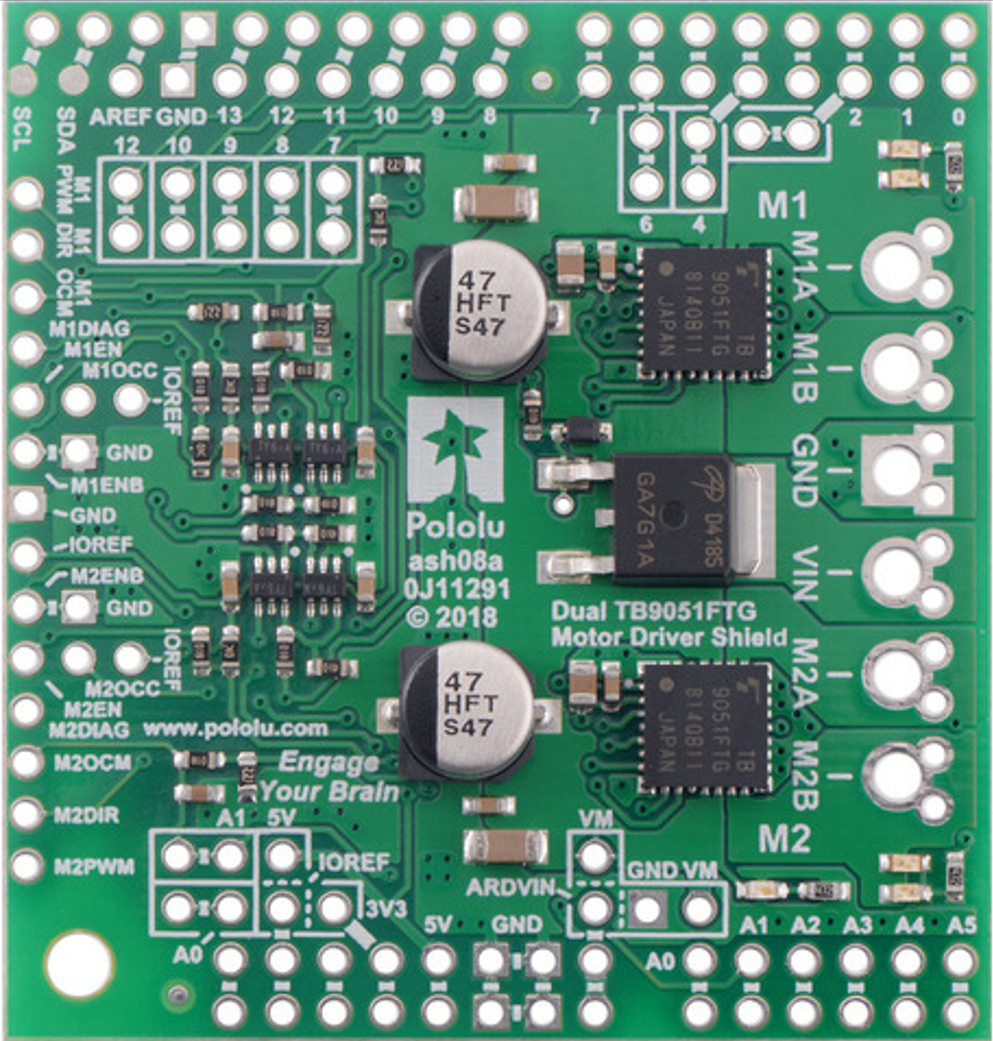
The Dual TB9051FTG Motor Driver Shield for Arduino, manufactured by Pololu, is a high-performance motor driver shield designed to control two DC motors. It is built around Toshiba's TB9051FTG motor driver IC, which offers high efficiency, low heat generation, and robust protection features. This shield is designed to integrate seamlessly with Arduino boards, making it an excellent choice for robotics, automation, and other motor control applications.
Explore Projects Built with Dual TB9051FTG Motor Driver Shield for Arduino
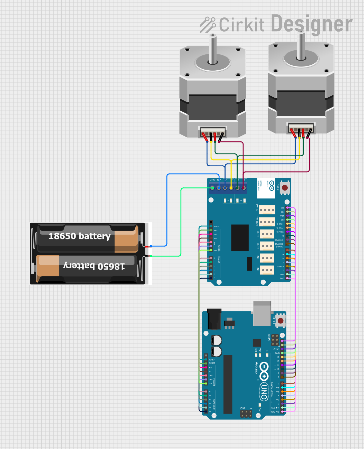

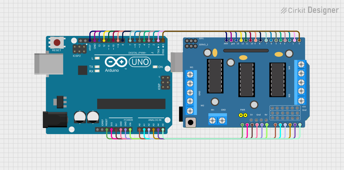
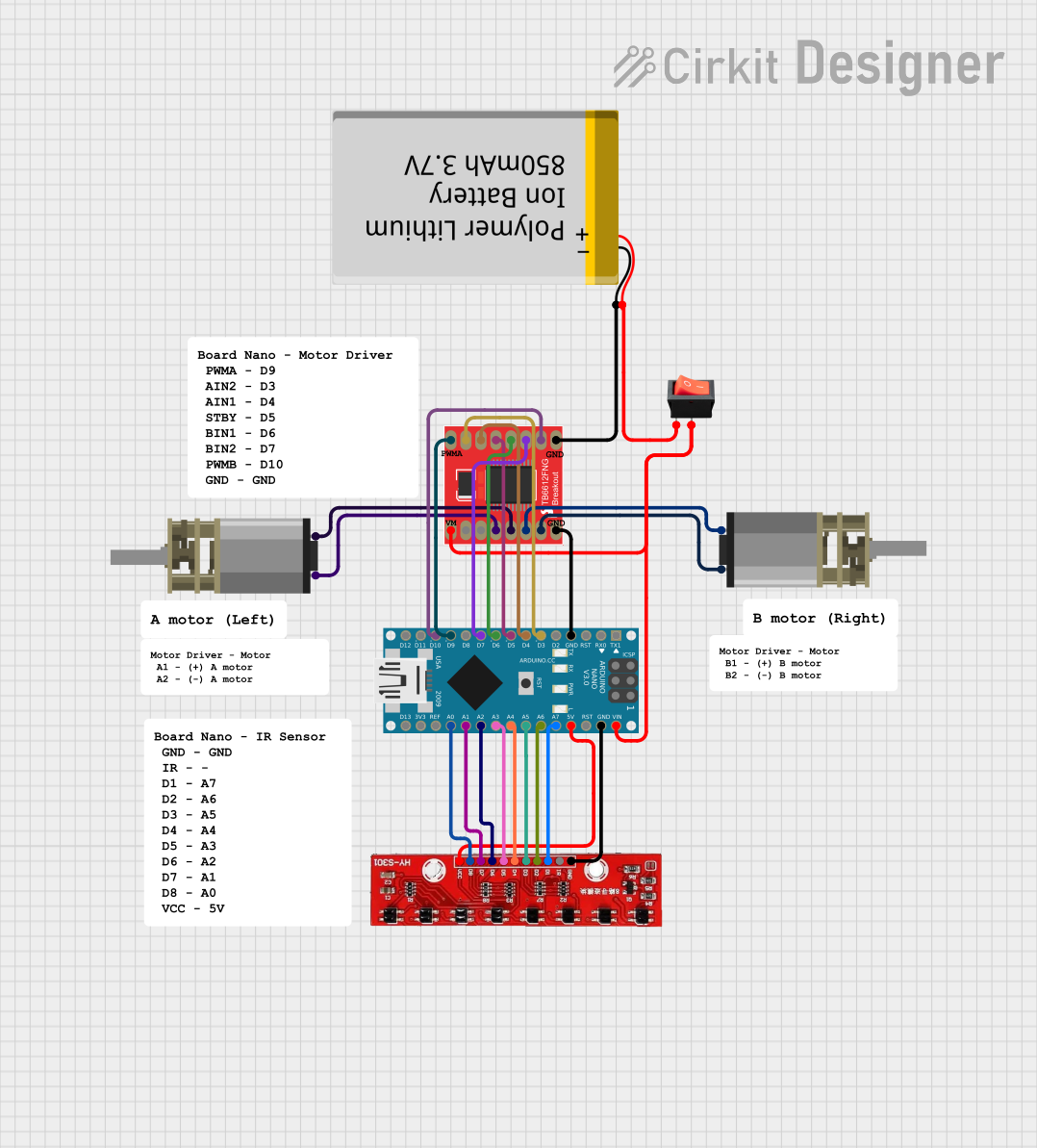
Explore Projects Built with Dual TB9051FTG Motor Driver Shield for Arduino
Common Applications and Use Cases
- Robotics projects requiring precise motor control
- Automated systems such as conveyor belts or robotic arms
- Remote-controlled vehicles and drones
- Educational projects for learning motor control with Arduino
- Prototyping motorized systems in industrial applications
Technical Specifications
The following are the key technical details of the Dual TB9051FTG Motor Driver Shield:
| Parameter | Specification |
|---|---|
| Operating Voltage | 4.5 V to 28 V |
| Continuous Output Current | 2.6 A per channel |
| Peak Output Current | 5 A per channel (short duration) |
| Logic Voltage | 3.3 V or 5 V (compatible with Arduino) |
| PWM Frequency | Up to 20 kHz |
| Motor Channels | 2 (independent control) |
| Protection Features | Overcurrent, overvoltage, undervoltage, |
| and overtemperature protection | |
| Dimensions | 68 mm × 53 mm |
Pin Configuration and Descriptions
The shield connects directly to an Arduino board, utilizing the standard Arduino pin headers. Below is a table describing the key pins and their functions:
| Pin | Function |
|---|---|
| VIN | Power input for motors (4.5 V to 28 V) |
| GND | Ground connection |
| AIN1, AIN2 | Control inputs for Motor A (direction control) |
| BIN1, BIN2 | Control inputs for Motor B (direction control) |
| PWMA | PWM input for Motor A speed control |
| PWMB | PWM input for Motor B speed control |
| DIAGA/DIAGB | Diagnostic outputs for Motor A and Motor B |
| ENA/ENB | Enable inputs for Motor A and Motor B |
| CS | Current sense output (shared for both motors) |
Usage Instructions
How to Use the Component in a Circuit
- Connect the Shield to an Arduino Board: Align the shield with the Arduino's pin headers and press it firmly into place.
- Power the Motors: Connect a power supply (4.5 V to 28 V) to the VIN and GND terminals on the shield. Ensure the power supply can provide sufficient current for your motors.
- Connect the Motors: Attach the two DC motors to the Motor A and Motor B output terminals on the shield.
- Program the Arduino: Use the Arduino IDE to write a program that controls the motors via the shield. The shield uses standard Arduino pins for PWM and direction control.
Important Considerations and Best Practices
- Power Supply: Ensure the power supply voltage matches the requirements of your motors and does not exceed the shield's maximum voltage rating.
- Heat Dissipation: While the TB9051FTG IC is efficient, prolonged high-current operation may generate heat. Consider adding a heatsink or ensuring proper ventilation.
- Protection Features: The shield includes built-in protection for overcurrent, overvoltage, undervoltage, and overtemperature. However, avoid intentionally exceeding the specified limits.
- Arduino Compatibility: The shield is compatible with most Arduino boards, including the Arduino UNO, Mega, and Leonardo.
Example Code for Arduino UNO
Below is an example Arduino sketch to control two motors using the shield:
// Example code for controlling two DC motors with the Dual TB9051FTG Motor Driver Shield

// Define motor control pins
const int AIN1 = 7;  // Motor A direction control pin 1
const int AIN2 = 8;  // Motor A direction control pin 2
const int PWMA = 9;  // Motor A speed control (PWM) pin
const int BIN1 = 4;  // Motor B direction control pin 1
const int BIN2 = 5;  // Motor B direction control pin 2
const int PWMB = 6;  // Motor B speed control (PWM) pin

void setup() {
  // Set motor control pins as outputs
  pinMode(AIN1, OUTPUT);
  pinMode(AIN2, OUTPUT);
  pinMode(PWMA, OUTPUT);
  pinMode(BIN1, OUTPUT);
  pinMode(BIN2, OUTPUT);
  pinMode(PWMB, OUTPUT);
}

void loop() {
  // Motor A: Forward at 50% speed
  digitalWrite(AIN1, HIGH);
  digitalWrite(AIN2, LOW);
  analogWrite(PWMA, 128);  // 50% duty cycle (128 out of 255)

  // Motor B: Reverse at 75% speed
  digitalWrite(BIN1, LOW);
  digitalWrite(BIN2, HIGH);
  analogWrite(PWMB, 192);  // 75% duty cycle (192 out of 255)

  delay(2000);  // Run motors for 2 seconds

  // Stop both motors
  analogWrite(PWMA, 0);
  analogWrite(PWMB, 0);

  delay(2000);  // Wait for 2 seconds before repeating
}
Troubleshooting and FAQs
Common Issues and Solutions
Motors Not Running:
- Ensure the power supply is connected to the VIN and GND terminals and is within the specified voltage range.
- Verify that the motor connections are secure and correctly wired.
- Check the Arduino code for errors in pin assignments or logic.
Overheating:
- Reduce the motor load or operating current.
- Ensure proper ventilation or add a heatsink to the TB9051FTG IC.
Erratic Motor Behavior:
- Check for loose connections or damaged wires.
- Verify that the power supply is stable and not fluctuating.
Diagnostic Pins Indicating Faults:
- Use the DIAGA and DIAGB pins to identify faults. A low signal on these pins indicates an error such as overcurrent or overtemperature.
FAQs
Q: Can I use this shield with stepper motors?
A: No, the Dual TB9051FTG Motor Driver Shield is designed for DC motors and is not suitable for stepper motors.
Q: What is the maximum PWM frequency supported?
A: The shield supports PWM frequencies up to 20 kHz, which is suitable for most motor control applications.
Q: Can I stack other shields on top of this one?
A: Yes, as long as the other shields do not conflict with the pins used by the motor driver shield.
Q: How do I monitor motor current?
A: The shield provides a current sense output (CS pin) that can be read using an analog input on the Arduino.