How to Use I2C: Examples, Pinouts, and Specs
Introduction
The I2C (Inter-Integrated Circuit), manufactured by Inter Integrated Circuit with part ID i2c, is a versatile, multi-master, multi-slave, packet-switched, single-ended serial communication bus. It is widely used for connecting low-speed devices such as sensors, EEPROMs, real-time clocks, and microcontrollers in embedded systems. I2C enables efficient communication between components using only two wires, making it ideal for applications where simplicity and low pin count are critical.
Explore Projects Built with I2C

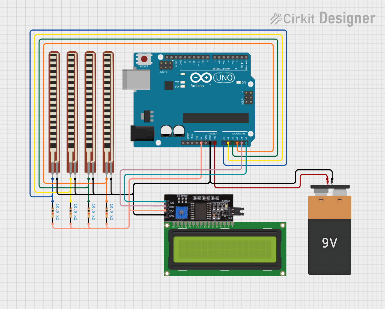
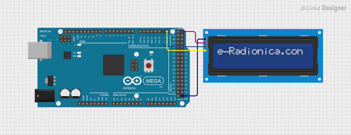
Explore Projects Built with I2C
Common Applications
- Communication between microcontrollers and peripheral devices (e.g., sensors, displays)
- Data transfer in embedded systems
- Interfacing EEPROMs, ADCs, and DACs
- Real-time clock (RTC) modules
- Consumer electronics (e.g., TVs, smartphones, and cameras)
Technical Specifications
Key Technical Details
| Parameter | Value/Description |
|---|---|
| Communication Type | Serial, synchronous |
| Number of Wires | 2 (SCL - Serial Clock Line, SDA - Serial Data Line) |
| Voltage Levels | Typically 3.3V or 5V |
| Data Transfer Rate | Standard Mode: 100 kbps, Fast Mode: 400 kbps |
| Maximum Devices | 127 devices (7-bit addressing) |
| Protocol Type | Multi-master, multi-slave |
| Pull-up Resistors | Required on both SCL and SDA lines |
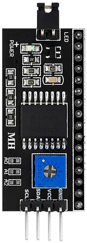
Pin Configuration and Descriptions
The I2C bus uses two main lines for communication:
| Pin Name | Description |
|---|---|
| SCL | Serial Clock Line: Carries the clock signal generated by the master device. |
| SDA | Serial Data Line: Transfers data between master and slave devices. |
Usage Instructions
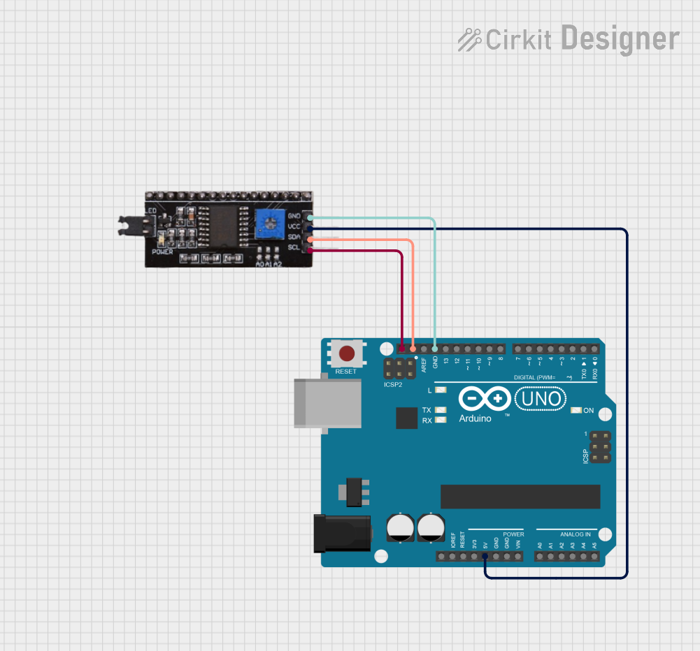
How to Use the I2C in a Circuit
Connect the I2C Lines:
- Connect the SCL and SDA lines of the master device (e.g., microcontroller) to the corresponding lines of the slave device(s).
- Use pull-up resistors (typically 4.7 kΩ or 10 kΩ) on both the SCL and SDA lines to ensure proper signal levels.
Power the Devices:
- Ensure all devices on the I2C bus share a common ground.
- Provide the appropriate operating voltage (e.g., 3.3V or 5V) to all devices.
Addressing:
- Assign a unique 7-bit address to each slave device.
- Ensure no two devices on the same bus share the same address.
Data Communication:
- The master initiates communication by sending a start condition, followed by the slave address and read/write bit.
- Data is transferred in 8-bit packets, with an acknowledgment (ACK) bit after each byte.
Important Considerations and Best Practices
- Pull-up Resistors: Always use pull-up resistors on the SCL and SDA lines to maintain proper logic levels.
- Bus Length: Keep the I2C bus as short as possible to minimize signal degradation and noise.
- Clock Speed: Ensure all devices on the bus support the selected clock speed (e.g., 100 kbps or 400 kbps).
- Address Conflicts: Verify that no two devices share the same address to avoid communication errors.
Example: Using I2C with Arduino UNO
Below is an example of interfacing an I2C temperature sensor with an Arduino UNO:
#include <Wire.h> // Include the Wire library for I2C communication

#define SENSOR_ADDRESS 0x48 // Replace with your sensor's I2C address

void setup() {
  Wire.begin(); // Initialize I2C communication
  Serial.begin(9600); // Start serial communication for debugging
}

void loop() {
  Wire.beginTransmission(SENSOR_ADDRESS); // Start communication with the sensor
  Wire.write(0x00); // Send a command to read temperature (example command)
  Wire.endTransmission(); // End transmission

  Wire.requestFrom(SENSOR_ADDRESS, 2); // Request 2 bytes of data from the sensor
  if (Wire.available() == 2) { // Check if 2 bytes are available
    int temp = Wire.read() << 8 | Wire.read(); // Combine the two bytes
    Serial.print("Temperature: ");
    Serial.println(temp / 256.0); // Convert and print the temperature
  }

  delay(1000); // Wait 1 second before the next reading
}
Troubleshooting and FAQs
Common Issues and Solutions
No Communication on the Bus:
- Cause: Missing or incorrect pull-up resistors.
- Solution: Ensure pull-up resistors (4.7 kΩ or 10 kΩ) are connected to both SCL and SDA lines.
Address Conflict:
- Cause: Two devices on the bus share the same address.
- Solution: Check and configure unique addresses for all devices.
Data Corruption:
- Cause: Excessive noise or long bus length.
- Solution: Shorten the bus length and use proper shielding.
Device Not Responding:
- Cause: Incorrect wiring or power supply issues.
- Solution: Verify connections and ensure all devices are powered correctly.
FAQs
Q1: Can I connect devices with different voltage levels on the same I2C bus?
A1: Yes, but you need a level shifter to safely interface devices operating at different voltage levels.
Q2: What happens if I don’t use pull-up resistors?
A2: Without pull-up resistors, the SCL and SDA lines may not reach the required logic high level, causing communication failures.
Q3: How many devices can I connect to the I2C bus?
A3: You can connect up to 127 devices using 7-bit addressing. However, practical limitations like bus capacitance may reduce this number.
Q4: Can I use multiple masters on the same I2C bus?
A4: Yes, I2C supports multi-master configurations, but arbitration is required to avoid conflicts.