How to Use GY_87: Examples, Pinouts, and Specs
Introduction
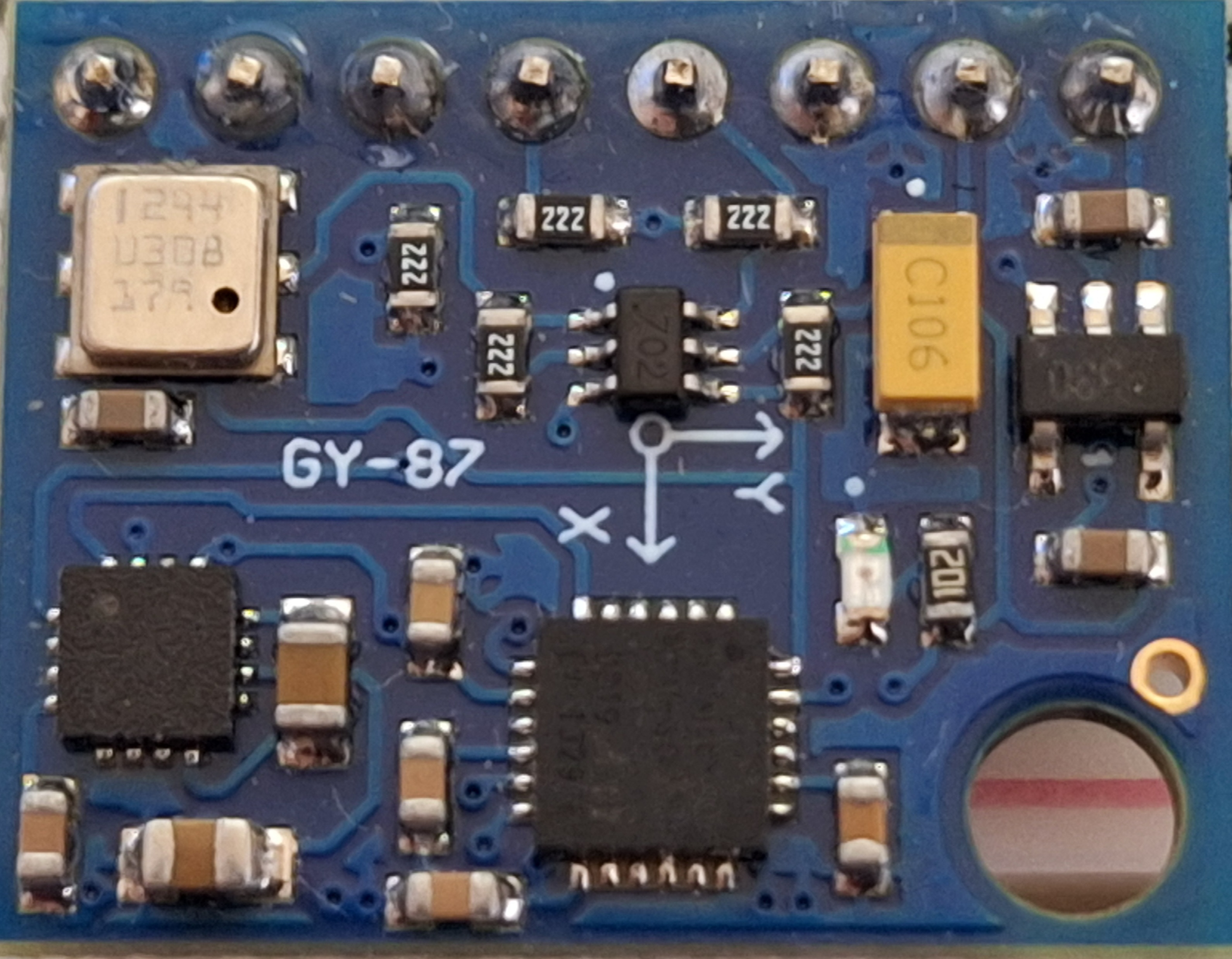
The GY-87 is a compact sensor module that integrates multiple motion and orientation sensors into a single board. It features a 3-axis accelerometer, a 3-axis gyroscope, and a 3-axis magnetometer, making it ideal for applications requiring precise motion tracking and orientation sensing. This module is widely used in robotics, drones, wearable devices, and other motion-sensitive systems.
The GY-87 is based on the MPU6050 (accelerometer and gyroscope) and the HMC5883L (magnetometer) chips, providing reliable and accurate data for a variety of projects. Its small size and I2C communication interface make it easy to integrate into microcontroller-based systems.
Explore Projects Built with GY_87
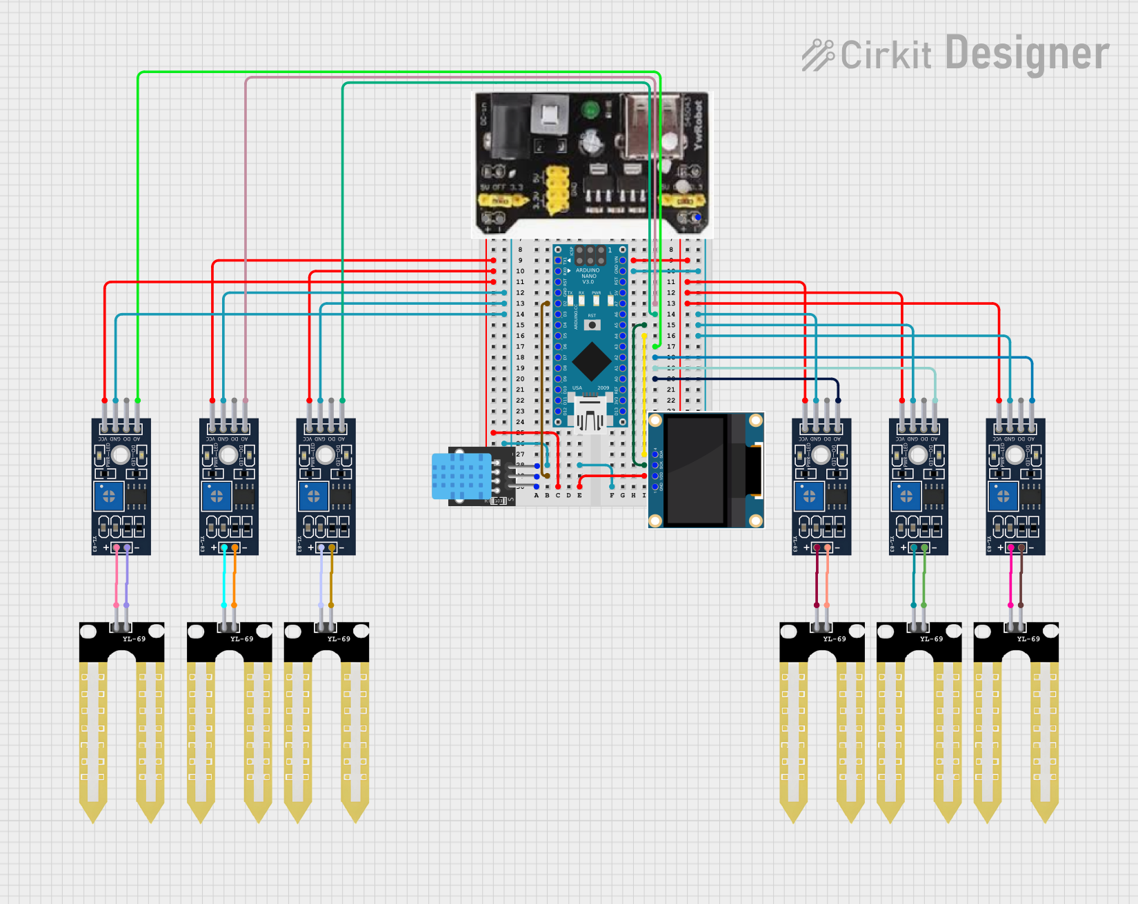
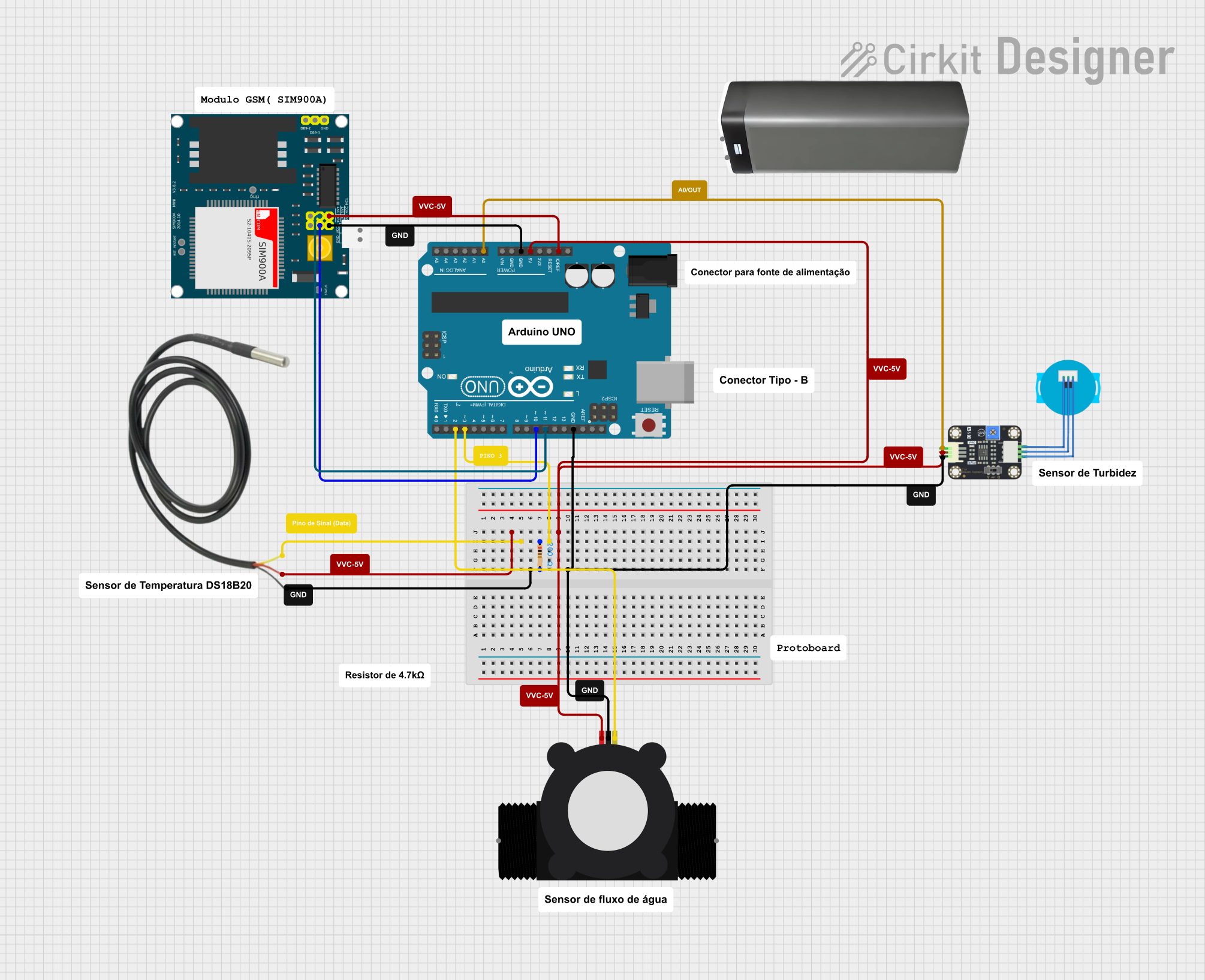

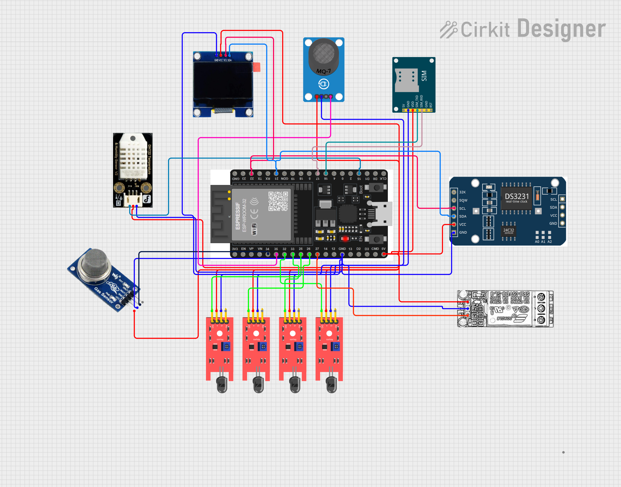
Explore Projects Built with GY_87
Technical Specifications
Key Technical Details
- Manufacturer: Unknown
- Manufacturer Part ID: MP085
- Supply Voltage: 3.3V to 5V
- Communication Interface: I2C
- Accelerometer Range: ±2g, ±4g, ±8g, ±16g
- Gyroscope Range: ±250°/s, ±500°/s, ±1000°/s, ±2000°/s
- Magnetometer Range: ±1.3 to ±8.1 Gauss
- Operating Temperature: -40°C to +85°C
- Dimensions: 20mm x 16mm
Pin Configuration and Descriptions
The GY-87 module has 6 pins, as described in the table below:
| Pin | Name | Description |
|---|---|---|
| 1 | VCC | Power supply input (3.3V to 5V). |
| 2 | GND | Ground connection. |
| 3 | SCL | I2C clock line. Used for communication with the microcontroller. |
| 4 | SDA | I2C data line. Used for communication with the microcontroller. |
| 5 | EDA | Auxiliary data line for the magnetometer (not commonly used). |
| 6 | ECL | Auxiliary clock line for the magnetometer (not commonly used). |
Usage Instructions
How to Use the GY-87 in a Circuit
- Power the Module: Connect the VCC pin to a 3.3V or 5V power source and the GND pin to ground.
- Connect I2C Lines: Connect the SCL and SDA pins to the corresponding I2C pins on your microcontroller. For an Arduino UNO, connect:
- SCL to A5
- SDA to A4
- Pull-Up Resistors: Ensure that the I2C lines (SCL and SDA) have pull-up resistors (typically 4.7kΩ). Some GY-87 modules include these resistors onboard.
- Initialize the Sensors: Use appropriate libraries to initialize and read data from the MPU6050 and HMC5883L sensors.
Important Considerations and Best Practices
- Voltage Compatibility: Ensure the module's voltage matches your microcontroller's I2C voltage levels. The GY-87 supports both 3.3V and 5V systems.
- I2C Address: The default I2C address for the MPU6050 is
0x68, and for the HMC5883L, it is0x1E. Verify these addresses in your code. - Calibration: Perform sensor calibration to improve accuracy, especially for the magnetometer and gyroscope.
- Mounting Orientation: Secure the module firmly to avoid vibrations, which can affect sensor readings.
Example Code for Arduino UNO
Below is an example code to read data from the MPU6050 (accelerometer and gyroscope) and HMC5883L (magnetometer) using the Arduino UNO:
#include <Wire.h>
#include <Adafruit_MPU6050.h>
#include <Adafruit_Sensor.h>
#include <Adafruit_HMC5883_U.h>

// Create sensor objects
Adafruit_MPU6050 mpu;
Adafruit_HMC5883_Unified mag = Adafruit_HMC5883_Unified(12345);

void setup() {
  Serial.begin(9600);
  while (!Serial) {
    delay(10); // Wait for Serial Monitor to open
  }

  // Initialize MPU6050
  if (!mpu.begin()) {
    Serial.println("Failed to find MPU6050 chip");
    while (1) {
      delay(10);
    }
  }
  Serial.println("MPU6050 initialized");

  // Initialize HMC5883L
  if (!mag.begin()) {
    Serial.println("Failed to find HMC5883L chip");
    while (1) {
      delay(10);
    }
  }
  Serial.println("HMC5883L initialized");
}

void loop() {
  // Read accelerometer and gyroscope data
  sensors_event_t a, g, temp;
  mpu.getEvent(&a, &g, &temp);

  // Print accelerometer data
  Serial.print("Accel X: "); Serial.print(a.acceleration.x);
  Serial.print(", Y: "); Serial.print(a.acceleration.y);
  Serial.print(", Z: "); Serial.println(a.acceleration.z);

  // Print gyroscope data
  Serial.print("Gyro X: "); Serial.print(g.gyro.x);
  Serial.print(", Y: "); Serial.print(g.gyro.y);
  Serial.print(", Z: "); Serial.println(g.gyro.z);

  // Read magnetometer data
  sensors_event_t event;
  mag.getEvent(&event);

  // Print magnetometer data
  Serial.print("Mag X: "); Serial.print(event.magnetic.x);
  Serial.print(", Y: "); Serial.print(event.magnetic.y);
  Serial.print(", Z: "); Serial.println(event.magnetic.z);

  delay(500); // Delay for readability
}
Troubleshooting and FAQs
Common Issues and Solutions
No Data from the Module:
- Ensure the module is powered correctly (check VCC and GND connections).
- Verify the I2C connections (SCL and SDA) and ensure pull-up resistors are present.
- Check the I2C addresses in your code. Use an I2C scanner sketch to detect the module.
Inaccurate Sensor Readings:
- Perform calibration for the accelerometer, gyroscope, and magnetometer.
- Minimize vibrations and secure the module firmly to avoid noise in the readings.
I2C Communication Errors:
- Ensure the I2C clock speed is compatible with the module (typically 100kHz or 400kHz).
- Check for conflicting I2C devices on the same bus.
FAQs
Can the GY-87 be used with 3.3V microcontrollers?
Yes, the GY-87 is compatible with both 3.3V and 5V systems.Do I need separate libraries for the MPU6050 and HMC5883L?
Yes, you will need libraries such asAdafruit_MPU6050andAdafruit_HMC5883_Uto interface with the sensors.How do I calibrate the sensors?
Use calibration routines provided in the sensor libraries or write custom calibration code to account for offsets and scaling factors.
By following this documentation, you can effectively integrate the GY-87 module into your projects and troubleshoot common issues.