Cirkit Designer Logo
Cirkit Designer
Your all-in-one circuit design IDE
Home / 
Component Documentation

How to Use Serial LCD Kit: Examples, Pinouts, and Specs

Image of Serial LCD Kit
Cirkit Designer LogoDesign with Serial LCD Kit in Cirkit Designer

Introduction

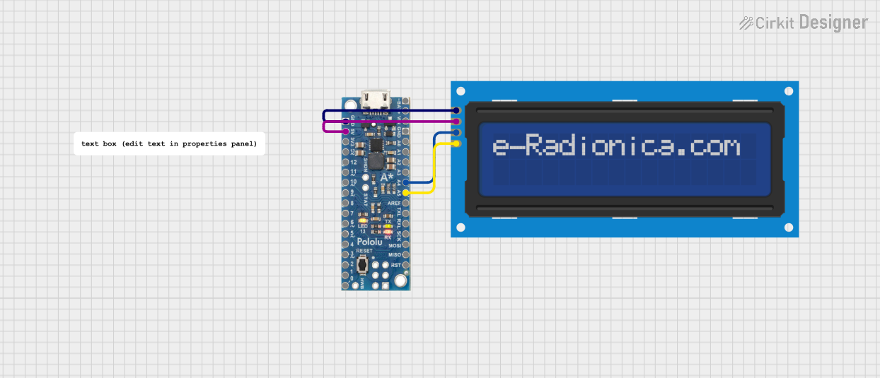
The Serial LCD Kit is a versatile and user-friendly module that enables the display of alphanumeric characters on an LCD. It incorporates a built-in controller, which simplifies the process of interfacing with various microcontrollers, including the popular Arduino platform. This module is commonly used in DIY electronics projects, hobbyist applications, and educational purposes to provide a visual output for data or user interface.

Explore Projects Built with Serial LCD Kit

Use Cirkit Designer to design, explore, and prototype these projects online. Some projects support real-time simulation. Click "Open Project" to start designing instantly!
ESP32 and I2C LCD Display for Data Visualization
Image of layar20x4I2C: A project utilizing Serial LCD Kit in a practical application
This circuit consists of an ESP32 Devkit V1 microcontroller connected to a 20x4 I2C LCD display. The ESP32 controls the LCD via I2C communication, with the SCL and SDA lines connected to GPIO pins D22 and D21, respectively, and provides power and ground connections to the display.
Cirkit Designer LogoOpen Project in Cirkit Designer
Arduino Leonardo Controlled I2C LCD Display for Text Scrolling
Image of final year project: A project utilizing Serial LCD Kit in a practical application
This circuit features an Arduino Leonardo microcontroller connected to a 16x2 I2C LCD screen, powered by a 5V battery. The Arduino is programmed to display and continuously scroll a message on the LCD. The I2C communication protocol is used for the microcontroller to interface with the LCD, utilizing the SDA and SCL connections for data transfer.
Cirkit Designer LogoOpen Project in Cirkit Designer
ESP32-Based OBD-II Car Speed Display with ILI9488 TFT Screen
Image of tachometr2: A project utilizing Serial LCD Kit in a practical application
This circuit connects an ESP32 Devkit V1 microcontroller to an LCD TFT screen using SPI communication for display purposes and to an OBD2 diagnostic tool for vehicle data retrieval. The ESP32 reads vehicle speed data from the OBD2 interface via UART and displays it on the LCD screen. The circuit is designed for automotive diagnostics, specifically to read and display real-time vehicle speed.
Cirkit Designer LogoOpen Project in Cirkit Designer
A-Star 32U4 Mini and I2C LCD Screen Battery-Powered Display
Image of lcd disolay: A project utilizing Serial LCD Kit in a practical application
This circuit features an A-Star 32U4 Mini microcontroller connected to a 16x2 I2C LCD screen. The microcontroller provides power and ground to the LCD, and communicates with it via the I2C protocol using the A4 (SDA) and A5 (SCL) pins.
Cirkit Designer LogoOpen Project in Cirkit Designer

Explore Projects Built with Serial LCD Kit

Use Cirkit Designer to design, explore, and prototype these projects online. Some projects support real-time simulation. Click "Open Project" to start designing instantly!
Image of layar20x4I2C: A project utilizing Serial LCD Kit in a practical application
ESP32 and I2C LCD Display for Data Visualization
This circuit consists of an ESP32 Devkit V1 microcontroller connected to a 20x4 I2C LCD display. The ESP32 controls the LCD via I2C communication, with the SCL and SDA lines connected to GPIO pins D22 and D21, respectively, and provides power and ground connections to the display.
Cirkit Designer LogoOpen Project in Cirkit Designer
Image of final year project: A project utilizing Serial LCD Kit in a practical application
Arduino Leonardo Controlled I2C LCD Display for Text Scrolling
This circuit features an Arduino Leonardo microcontroller connected to a 16x2 I2C LCD screen, powered by a 5V battery. The Arduino is programmed to display and continuously scroll a message on the LCD. The I2C communication protocol is used for the microcontroller to interface with the LCD, utilizing the SDA and SCL connections for data transfer.
Cirkit Designer LogoOpen Project in Cirkit Designer
Image of tachometr2: A project utilizing Serial LCD Kit in a practical application
ESP32-Based OBD-II Car Speed Display with ILI9488 TFT Screen
This circuit connects an ESP32 Devkit V1 microcontroller to an LCD TFT screen using SPI communication for display purposes and to an OBD2 diagnostic tool for vehicle data retrieval. The ESP32 reads vehicle speed data from the OBD2 interface via UART and displays it on the LCD screen. The circuit is designed for automotive diagnostics, specifically to read and display real-time vehicle speed.
Cirkit Designer LogoOpen Project in Cirkit Designer
Image of lcd disolay: A project utilizing Serial LCD Kit in a practical application
A-Star 32U4 Mini and I2C LCD Screen Battery-Powered Display
This circuit features an A-Star 32U4 Mini microcontroller connected to a 16x2 I2C LCD screen. The microcontroller provides power and ground to the LCD, and communicates with it via the I2C protocol using the A4 (SDA) and A5 (SCL) pins.
Cirkit Designer LogoOpen Project in Cirkit Designer

Common Applications and Use Cases

  • Displaying sensor readings
  • Creating user interfaces for projects
  • Showing status messages and debug information
  • Building clocks, timers, or counters

Technical Specifications

Key Technical Details

  • Operating Voltage: Typically 5V
  • Display: 16x2 or 20x4 characters (depending on model)
  • Backlight: LED, usually blue or green
  • Communication: Serial (TTL level)
  • Baud Rate: Configurable, commonly 9600 bps

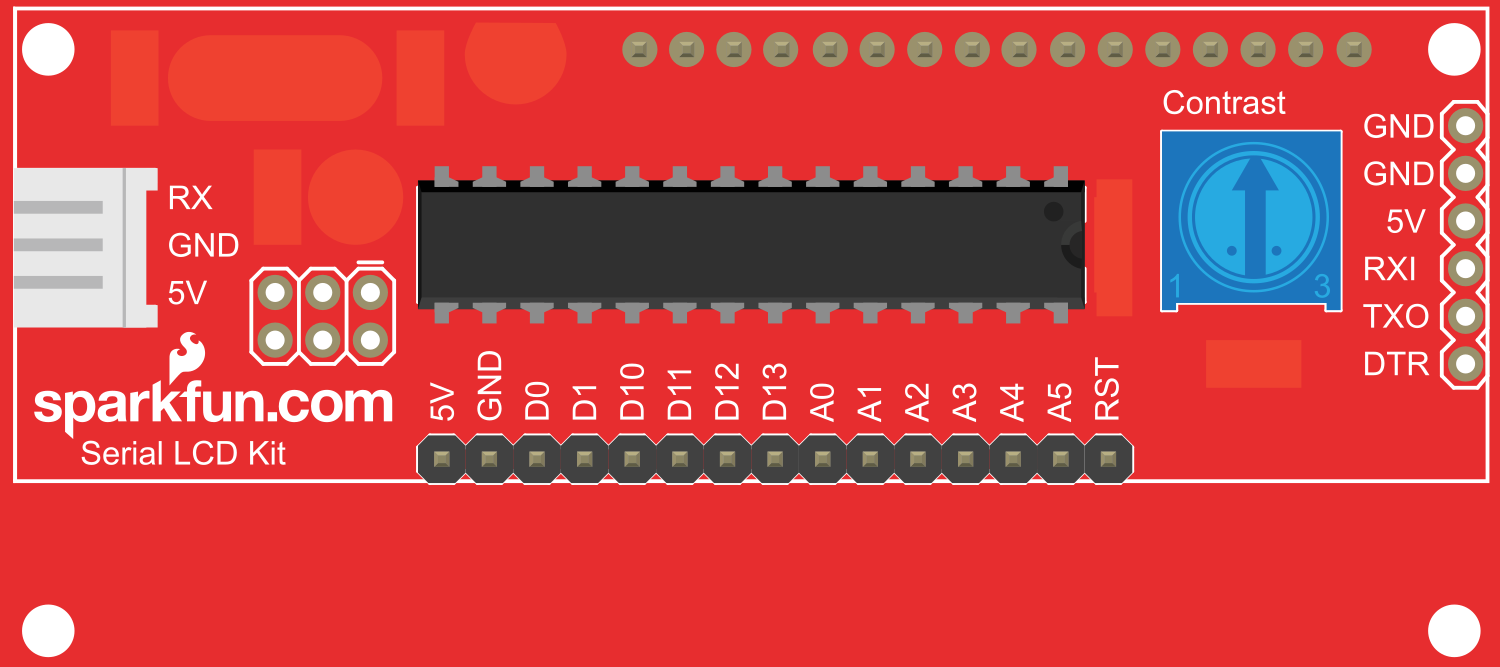
Pin Configuration and Descriptions

Pin Number Name Description
1 VCC Power supply (5V)
2 GND Ground connection
3 RX Serial receive pin
4 TX Serial transmit pin (not always used)
5 BL Backlight control (optional)

Usage Instructions

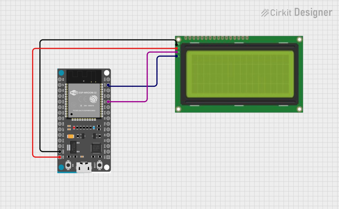
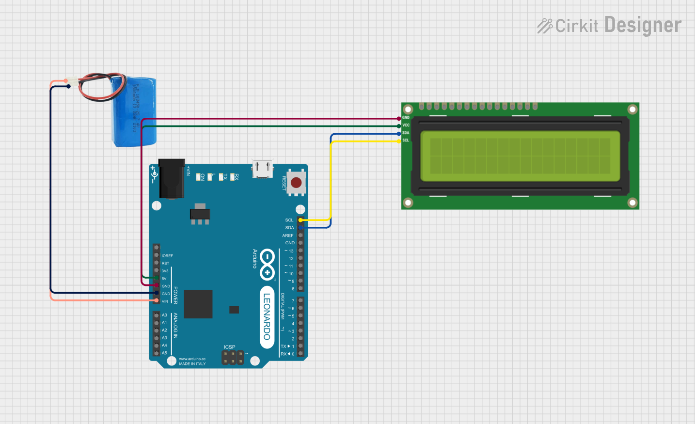
Interfacing with a Microcontroller

  1. Connect the VCC pin to the 5V output on the microcontroller.
  2. Connect the GND pin to a ground pin on the microcontroller.
  3. Connect the RX pin on the Serial LCD to a TX pin on the microcontroller.
  4. (Optional) Connect the BL pin to a digital pin on the microcontroller if backlight control is required.

Important Considerations and Best Practices

  • Always ensure that the power supply voltage matches the requirements of the Serial LCD Kit.
  • Avoid connecting or disconnecting the Serial LCD while the power is on to prevent damage.
  • Use a current-limiting resistor if you are controlling the backlight brightness with a microcontroller pin.

Example Code for Arduino UNO

#include <SoftwareSerial.h>

// Initialize the software serial connection
SoftwareSerial serialLCD(10, 11); // RX, TX

void setup() {
  // Set the baud rate for the serial connection
  serialLCD.begin(9600);
  
  // Clear the screen
  serialLCD.write(0xFE);
  serialLCD.write(0x01);
}

void loop() {
  // Send a string to the LCD
  serialLCD.write("Hello, World!");
  
  // Wait for a while
  delay(3000);
  
  // Clear the screen before the next message
  serialLCD.write(0xFE);
  serialLCD.write(0x01);
  
  // Send another string to the LCD
  serialLCD.write("Serial LCD Kit");
  
  // Wait again
  delay(3000);
}

Note: The SoftwareSerial library is used to create a serial communication on digital pins 10 and 11, where pin 10 is defined as RX and pin 11 as TX. However, only the TX pin from Arduino is connected to the RX pin of the Serial LCD Kit.

Troubleshooting and FAQs

Common Issues

  • Display not powering on: Check connections to VCC and GND, and ensure the power supply is at the correct voltage.
  • Garbled or no text on display: Verify the baud rate settings and connections between the microcontroller's TX pin and the LCD's RX pin.
  • Backlight not working: If using the BL pin, ensure it is connected correctly and controlled via the microcontroller.

Solutions and Tips for Troubleshooting

  • Double-check all wiring connections.
  • Make sure the Serial LCD Kit is configured to the same baud rate as the microcontroller.
  • If using the backlight control, test the pin with a simple LED circuit to ensure it is functioning correctly.

FAQs

Q: Can I use the Serial LCD Kit with a 3.3V system? A: It depends on the specific model of the Serial LCD Kit. Some may work at 3.3V, but level shifting may be required for proper operation.

Q: How do I adjust the contrast of the display? A: Contrast is typically adjusted via a potentiometer on the back of the LCD module. Turn the potentiometer until the desired contrast is achieved.

Q: Can I display custom characters or graphics? A: The Serial LCD Kit usually supports custom characters. Refer to the specific controller datasheet for instructions on how to create and display them.