Cirkit Designer Logo
Cirkit Designer
Your all-in-one circuit design IDE
Home / 
Component Documentation

How to Use Grove GPS : Examples, Pinouts, and Specs

Image of Grove GPS
Cirkit Designer LogoDesign with Grove GPS in Cirkit Designer

Introduction

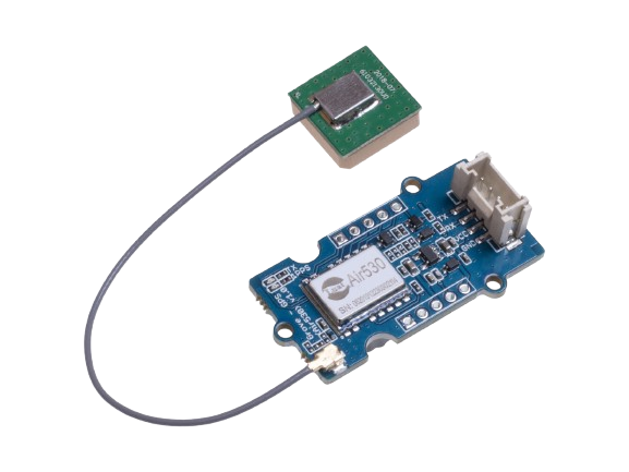
The Grove GPS module, manufactured by Seeed Studio with part ID Air530z, is a high-performance GPS module designed to provide accurate location data by communicating with satellites. This module is commonly used in navigation systems, geolocation projects, and various applications requiring precise positioning information. It outputs data such as latitude, longitude, altitude, speed, and time.

Explore Projects Built with Grove GPS

Use Cirkit Designer to design, explore, and prototype these projects online. Some projects support real-time simulation. Click "Open Project" to start designing instantly!
ESP32-Based GPS Tracker with OLED Display and Telegram Integration
Image of Yoon: A project utilizing Grove GPS  in a practical application
This circuit is a GPS-based tracking system that uses an ESP32 microcontroller to receive GPS data from a NEO 6M module and display the coordinates on a 1.3" OLED screen. It also features WiFi connectivity to send location updates to a remote server, potentially for applications such as asset tracking or navigation assistance.
Cirkit Designer LogoOpen Project in Cirkit Designer
ESP32-Based GPS Tracker with OLED Display and Firebase Integration
Image of ecs: A project utilizing Grove GPS  in a practical application
This circuit is a GPS tracking system that uses an ESP32 microcontroller to read location data from a NEO-6M GPS module and display information on a 0.96" OLED screen. The system is powered by a 2000mAh battery with a lithium-ion charger, and it uploads the GPS data to Firebase via WiFi. Additional components include an MPU6050 accelerometer/gyroscope for motion sensing and a buzzer for alerts.
Cirkit Designer LogoOpen Project in Cirkit Designer
Arduino UNO with A9G GSM/GPRS and Dual VL53L1X Distance Sensors
Image of TED CIRCUIT : A project utilizing Grove GPS  in a practical application
This circuit features an Arduino UNO microcontroller interfaced with an A9G GSM/GPRS+GPS/BDS module and two VL53L1X time-of-flight distance sensors. The A9G module is connected to the Arduino via serial communication for GPS and GSM functionalities, while both VL53L1X sensors are connected through I2C with shared SDA and SCL lines and individual SHUT pins for selective sensor activation. The Arduino is programmed to control these peripherals, although the specific functionality is not detailed in the provided code.
Cirkit Designer LogoOpen Project in Cirkit Designer
ESP32-Based Weather Station with GPS and SD Card Storage
Image of ACP_Circuit: A project utilizing Grove GPS  in a practical application
This circuit is a data logging system that uses an ESP32 microcontroller to collect environmental data from a DHT11 humidity and temperature sensor and GPS location data from a Grove GPS module. The collected data is stored on a Micro SD card, and the entire system is powered by a DC power source through a DC buck step-down converter.
Cirkit Designer LogoOpen Project in Cirkit Designer

Explore Projects Built with Grove GPS

Use Cirkit Designer to design, explore, and prototype these projects online. Some projects support real-time simulation. Click "Open Project" to start designing instantly!
Image of Yoon: A project utilizing Grove GPS  in a practical application
ESP32-Based GPS Tracker with OLED Display and Telegram Integration
This circuit is a GPS-based tracking system that uses an ESP32 microcontroller to receive GPS data from a NEO 6M module and display the coordinates on a 1.3" OLED screen. It also features WiFi connectivity to send location updates to a remote server, potentially for applications such as asset tracking or navigation assistance.
Cirkit Designer LogoOpen Project in Cirkit Designer
Image of ecs: A project utilizing Grove GPS  in a practical application
ESP32-Based GPS Tracker with OLED Display and Firebase Integration
This circuit is a GPS tracking system that uses an ESP32 microcontroller to read location data from a NEO-6M GPS module and display information on a 0.96" OLED screen. The system is powered by a 2000mAh battery with a lithium-ion charger, and it uploads the GPS data to Firebase via WiFi. Additional components include an MPU6050 accelerometer/gyroscope for motion sensing and a buzzer for alerts.
Cirkit Designer LogoOpen Project in Cirkit Designer
Image of TED CIRCUIT : A project utilizing Grove GPS  in a practical application
Arduino UNO with A9G GSM/GPRS and Dual VL53L1X Distance Sensors
This circuit features an Arduino UNO microcontroller interfaced with an A9G GSM/GPRS+GPS/BDS module and two VL53L1X time-of-flight distance sensors. The A9G module is connected to the Arduino via serial communication for GPS and GSM functionalities, while both VL53L1X sensors are connected through I2C with shared SDA and SCL lines and individual SHUT pins for selective sensor activation. The Arduino is programmed to control these peripherals, although the specific functionality is not detailed in the provided code.
Cirkit Designer LogoOpen Project in Cirkit Designer
Image of ACP_Circuit: A project utilizing Grove GPS  in a practical application
ESP32-Based Weather Station with GPS and SD Card Storage
This circuit is a data logging system that uses an ESP32 microcontroller to collect environmental data from a DHT11 humidity and temperature sensor and GPS location data from a Grove GPS module. The collected data is stored on a Micro SD card, and the entire system is powered by a DC power source through a DC buck step-down converter.
Cirkit Designer LogoOpen Project in Cirkit Designer

Technical Specifications

Key Technical Details

Specification Value
Manufacturer Seeed Studio
Part ID Air530z
Voltage Range 3.3V - 5V
Current Consumption 30mA (typical)
Communication UART (9600 bps default)
Position Accuracy 2.5m CEP
Cold Start Time 30s (typical)
Hot Start Time 1s (typical)
Operating Temperature -40°C to +85°C
Dimensions 40mm x 20mm

Pin Configuration and Descriptions

Pin Number Pin Name Description
1 VCC Power supply (3.3V - 5V)
2 GND Ground
3 RX UART Receive (connect to TX of MCU)
4 TX UART Transmit (connect to RX of MCU)

Usage Instructions

How to Use the Component in a Circuit

  1. Power Supply: Connect the VCC pin to a 3.3V or 5V power supply and the GND pin to the ground.
  2. UART Communication: Connect the RX pin of the GPS module to the TX pin of your microcontroller (e.g., Arduino UNO) and the TX pin of the GPS module to the RX pin of your microcontroller.
  3. Antenna: Ensure the GPS module has a clear view of the sky for optimal satellite communication.

Important Considerations and Best Practices

  • Antenna Placement: For best performance, place the GPS module in an open area with a clear view of the sky to avoid signal obstructions.
  • Power Supply: Ensure a stable power supply to avoid fluctuations that can affect the GPS module's performance.
  • UART Settings: The default baud rate is 9600 bps. Ensure your microcontroller's UART settings match this baud rate.

Example Code for Arduino UNO

#include <SoftwareSerial.h>

// Create a software serial port on pins 4 (RX) and 3 (TX)
SoftwareSerial gpsSerial(4, 3);

void setup() {
  // Start the hardware serial port for communication with the PC
  Serial.begin(9600);
  // Start the software serial port for communication with the GPS module
  gpsSerial.begin(9600);
}

void loop() {
  // Check if data is available from the GPS module
  while (gpsSerial.available()) {
    // Read a byte from the GPS module
    char c = gpsSerial.read();
    // Print the byte to the hardware serial port
    Serial.print(c);
  }
}

Troubleshooting and FAQs

Common Issues Users Might Face

  1. No GPS Fix: The GPS module is not able to get a fix on the satellites.

    • Solution: Ensure the module has a clear view of the sky. Move to an open area if necessary.
  2. No Data Output: The GPS module is not outputting any data.

    • Solution: Check the power connections and ensure the module is properly powered. Verify the UART connections and baud rate settings.
  3. Intermittent Data: The data from the GPS module is intermittent or unreliable.

    • Solution: Ensure a stable power supply and check for any loose connections. Verify that the antenna is properly placed.

Solutions and Tips for Troubleshooting

  • Check Connections: Ensure all connections are secure and correctly placed.
  • Verify Power Supply: Use a stable power source within the specified voltage range.
  • Match Baud Rate: Ensure the baud rate of the GPS module matches the microcontroller's UART settings.
  • Antenna Positioning: Place the GPS module in an open area with a clear view of the sky for optimal performance.

By following these guidelines and best practices, you can effectively integrate the Grove GPS module into your projects and achieve accurate and reliable geolocation data.