
How to Use ZVS Induction Board 1000w 20A: Examples, Pinouts, and Specs
 Design with ZVS Induction Board 1000w 20A in Cirkit Designer
Introduction
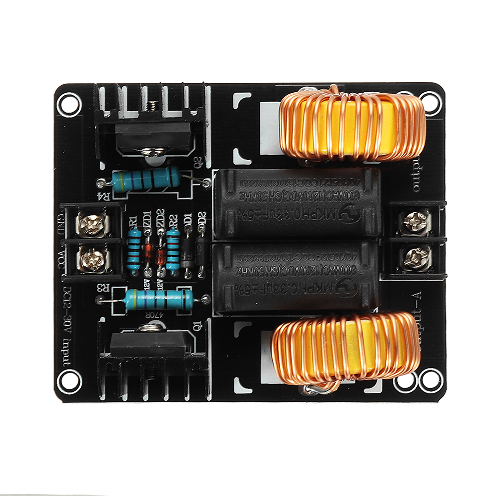
The ZVS Induction Board 1000W 20A by Elecbee is a high-efficiency Zero Voltage Switching (ZVS) module designed for induction heating applications. This board is capable of delivering up to 1000 watts of power at a maximum current of 20 amps, making it ideal for tasks such as induction cooking, metal melting, and small-scale industrial heating processes. Its ZVS design ensures minimal switching losses, resulting in higher efficiency and reduced heat generation.
Explore Projects Built with ZVS Induction Board 1000w 20A
 Open Project in Cirkit Designer
 Open Project in Cirkit Designer
 Open Project in Cirkit Designer
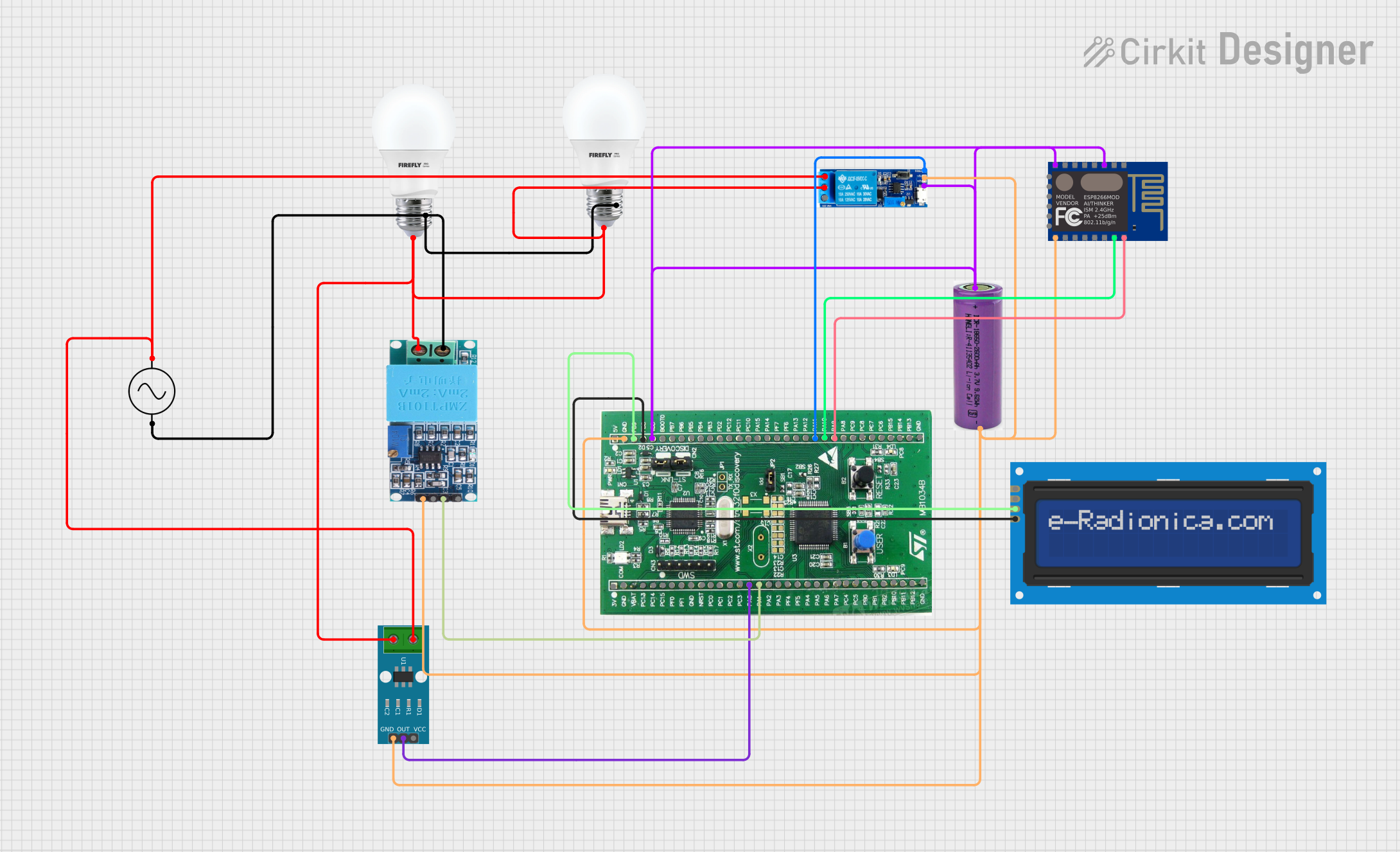 Open Project in Cirkit Designer
Explore Projects Built with ZVS Induction Board 1000w 20A
Open Project in Cirkit DesignerOpen Project in Cirkit DesignerOpen Project in Cirkit DesignerOpen Project in Cirkit DesignerCommon Applications
- Induction cooking stoves
- Metal melting and forging
- Heat treatment of small metal parts
- DIY induction heating projects
- Scientific experiments requiring high-frequency heating
Technical Specifications
Key Specifications
| Parameter | Value |
|---|---|
| Input Voltage Range | 12V to 48V DC |
| Maximum Power Output | 1000W |
| Maximum Current | 20A |
| Operating Frequency | 30kHz to 50kHz (approximate) |
| Efficiency | >90% |
| Cooling Requirements | External cooling recommended |
| Dimensions | 100mm x 80mm x 50mm |
Pin Configuration and Descriptions
The ZVS Induction Board has the following key connections:
| Pin/Terminal | Description |
|---|---|
| V+ | Positive DC input voltage (12V to 48V). Connect to the positive terminal of the power supply. |
| V- | Negative DC input voltage (ground). Connect to the negative terminal of the power supply. |
| Output Coil | Two terminals for connecting the induction heating coil. Ensure proper connection for optimal performance. |
Note: The board does not include reverse polarity protection. Ensure correct polarity when connecting the power supply to avoid damage.
Usage Instructions
How to Use the ZVS Induction Board in a Circuit
Power Supply Selection:
- Use a DC power supply capable of delivering the required voltage (12V to 48V) and current (up to 20A).
- Ensure the power supply has sufficient capacity to handle the board's maximum power output.
Connecting the Induction Coil:
- Attach the two terminals of the induction heating coil to the output coil connectors on the board.
- Use a coil with appropriate inductance and resistance for the desired heating application.
Cooling Requirements:
- The board generates heat during operation. Attach a heatsink to the MOSFETs and use an external cooling fan to prevent overheating.
- Monitor the temperature of the board during operation to ensure it remains within safe limits.
Powering the Board:
- Connect the V+ and V- terminals to the power supply, ensuring correct polarity.
- Gradually increase the input voltage to the desired level for your application.
Testing and Operation:
- Place the object to be heated inside the induction coil.
- Turn on the power supply and observe the heating process. Adjust the input voltage as needed to control the heating intensity.
Important Considerations and Best Practices
- Avoid Overloading: Do not exceed the maximum power or current ratings of the board.
- Proper Cooling: Always use adequate cooling to prevent damage to the MOSFETs and other components.
- Coil Selection: Use a coil with appropriate dimensions and material for your application. Avoid using coils with very low resistance, as this may cause excessive current draw.
- Safety Precautions: Induction heating generates high temperatures. Handle heated objects with care and avoid direct contact with the coil during operation.
Example: Using the ZVS Induction Board with an Arduino UNO
While the ZVS Induction Board is typically used as a standalone module, it can be controlled using an Arduino UNO for automated applications. Below is an example of how to control the power supply to the board using a relay module:
// Example Arduino code to control the ZVS Induction Board using a relay module
// This code turns the induction board on and off at regular intervals.

const int relayPin = 7; // Pin connected to the relay module

void setup() {
  pinMode(relayPin, OUTPUT); // Set the relay pin as an output
  digitalWrite(relayPin, LOW); // Ensure the relay is off initially
}

void loop() {
  digitalWrite(relayPin, HIGH); // Turn on the relay (power to ZVS board)
  delay(5000); // Keep the board on for 5 seconds

  digitalWrite(relayPin, LOW); // Turn off the relay (cut power to ZVS board)
  delay(5000); // Keep the board off for 5 seconds
}
Note: Ensure the relay module is rated for the voltage and current of the ZVS Induction Board's power supply.
Troubleshooting and FAQs
Common Issues and Solutions
| Issue | Possible Cause | Solution |
|---|---|---|
| Board does not power on | Incorrect power supply connection | Verify the polarity and voltage of the power supply. |
| Excessive heat generation | Insufficient cooling | Attach a heatsink and use a cooling fan. |
| Poor heating performance | Incompatible coil or low input voltage | Use a properly designed coil and ensure sufficient input voltage. |
| MOSFETs damaged | Overloading or reverse polarity | Avoid exceeding the board's ratings and ensure correct polarity. |
FAQs
Can I use a battery to power the ZVS Induction Board?
- Yes, you can use a high-capacity battery capable of delivering the required voltage and current. Ensure the battery can handle the board's maximum power output.
What type of coil should I use?
- Use an induction coil made of copper tubing or wire with appropriate dimensions for your application. The coil should have sufficient inductance and low resistance.
How do I prevent the board from overheating?
- Use a heatsink and cooling fan to dissipate heat. Monitor the board's temperature during operation and avoid prolonged use at maximum power.
Can I control the board's power output?
- The power output can be adjusted by varying the input voltage. Use a variable power supply for precise control.
By following this documentation, you can safely and effectively use the ZVS Induction Board 1000W 20A for your induction heating projects.