How to Use Servo Internal Circuit: Examples, Pinouts, and Specs
Introduction
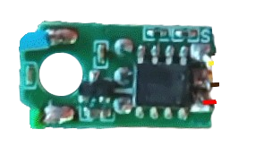
A servo internal circuit is an essential electronic component within a servo motor that controls its position, speed, and torque. This circuit typically includes a potentiometer, a control circuit, and a motor driver to ensure precise movement based on input signals. Servo motors are widely used in various applications, including robotics, remote-controlled vehicles, and industrial automation, due to their ability to provide accurate and controlled motion.
Explore Projects Built with Servo Internal Circuit

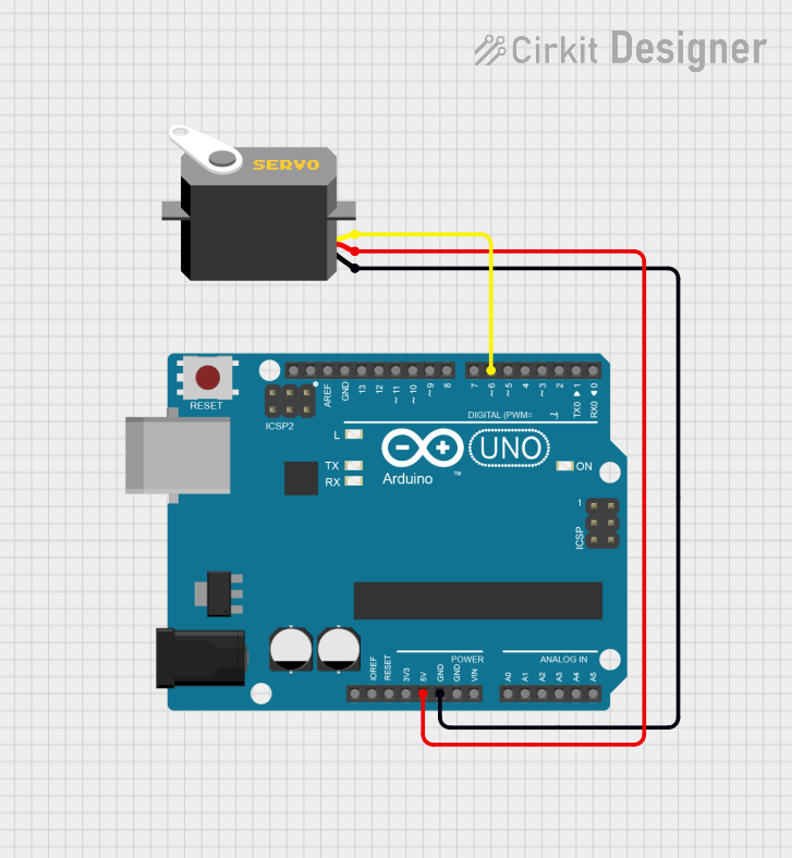
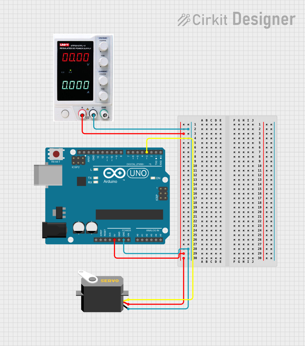
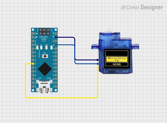
Explore Projects Built with Servo Internal Circuit
Technical Specifications
Key Technical Details
| Parameter | Value |
|---|---|
| Operating Voltage | 4.8V to 6.0V |
| Operating Current | 100mA to 1A (depending on load) |
| Control Signal | PWM (Pulse Width Modulation) |
| PWM Frequency | 50Hz |
| Position Range | 0° to 180° |
| Torque | Varies by model (e.g., 1.5kg/cm to 20kg/cm) |
Pin Configuration and Descriptions
| Pin Number | Pin Name | Description |
|---|---|---|
| 1 | GND | Ground connection |
| 2 | VCC | Power supply (4.8V to 6.0V) |
| 3 | Signal | PWM control signal input |
Usage Instructions
How to Use the Component in a Circuit
- Power Supply: Connect the VCC pin to a 5V power supply and the GND pin to the ground of your circuit.
- Control Signal: Connect the Signal pin to a PWM output pin of a microcontroller (e.g., Arduino UNO).
- PWM Signal: Generate a PWM signal with a frequency of 50Hz. The duty cycle of the PWM signal will determine the position of the servo motor. A 1ms pulse typically corresponds to 0°, a 1.5ms pulse to 90°, and a 2ms pulse to 180°.
Important Considerations and Best Practices
- Power Supply: Ensure that the power supply can provide sufficient current for the servo motor, especially under load conditions.
- Signal Integrity: Use short and shielded wires for the signal connection to avoid noise and interference.
- Heat Dissipation: If the servo motor is used continuously or under heavy load, ensure proper ventilation and cooling to prevent overheating.
Example Circuit with Arduino UNO
#include <Servo.h> // Include the Servo library

Servo myServo; // Create a Servo object

void setup() {
  myServo.attach(9); // Attach the servo to pin 9 on the Arduino UNO
}

void loop() {
  myServo.write(0); // Move the servo to 0 degrees
  delay(1000); // Wait for 1 second
  myServo.write(90); // Move the servo to 90 degrees
  delay(1000); // Wait for 1 second
  myServo.write(180); // Move the servo to 180 degrees
  delay(1000); // Wait for 1 second
}
Troubleshooting and FAQs
Common Issues Users Might Face
Servo Not Moving:
- Solution: Check the power supply connections and ensure that the PWM signal is being generated correctly.
Jittery Movement:
- Solution: Ensure that the signal wire is not picking up noise. Use short and shielded wires if necessary.
Overheating:
- Solution: Ensure that the servo is not stalled or under excessive load. Provide adequate cooling and ventilation.
FAQs
Can I use a higher voltage power supply?
- No, using a higher voltage than specified (4.8V to 6.0V) can damage the servo motor.
What is the maximum angle the servo can rotate?
- Most standard servo motors can rotate from 0° to 180°, but some models may have a different range.
How do I control the speed of the servo?
- The speed of the servo is controlled by the rate at which you change the PWM signal. Gradual changes in the PWM signal will result in slower movement.
By following this documentation, users can effectively integrate and troubleshoot a servo internal circuit in their projects, ensuring precise and reliable motion control.