Cirkit Designer Logo
Cirkit Designer
Your all-in-one circuit design IDE
Home / 
Component Documentation

How to Use GY-BME280 3V3: Examples, Pinouts, and Specs

Image of GY-BME280 3V3
Cirkit Designer LogoDesign with GY-BME280 3V3 in Cirkit Designer

Introduction

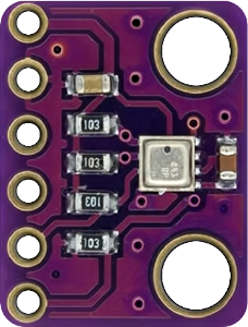
The GY-BME280 3V3 is a compact digital sensor module designed for measuring temperature, humidity, and atmospheric pressure. Manufactured in China, this versatile sensor operates at 3.3V and supports both I2C and SPI communication protocols, making it an excellent choice for environmental monitoring applications. Its high precision and low power consumption make it ideal for use in weather stations, IoT devices, HVAC systems, and altitude measurement projects.

Explore Projects Built with GY-BME280 3V3

Use Cirkit Designer to design, explore, and prototype these projects online. Some projects support real-time simulation. Click "Open Project" to start designing instantly!
ESP32-Based Environmental Monitoring System with Solar Charging
Image of IoT Ola (Final): A project utilizing GY-BME280 3V3 in a practical application
This circuit features an ESP32 microcontroller interfaced with a BME/BMP280 sensor for environmental monitoring and an MH-Z19B sensor for CO2 measurement, both communicating via I2C (SCL, SDA) and serial (TX, RX) connections respectively. It includes a SIM800L module for GSM communication, connected to the ESP32 via serial (TXD, RXD). Power management is handled by two TP4056 modules for charging 18650 Li-ion batteries via solar panels, with a step-up boost converter to provide consistent voltage to the MH-Z19B, and voltage regulation for the SIM800L. Decoupling capacitors are used to stabilize the power supply to the BME/BMP280 and ESP32.
Cirkit Designer LogoOpen Project in Cirkit Designer
ESP8266-Based Environmental Monitoring System
Image of Stacja_Pogodowa1: A project utilizing GY-BME280 3V3 in a practical application
This circuit is designed to collect environmental data using an ESP-8266 microcontroller connected to a BMP180 barometric pressure sensor, a GY-30 BH1750FVI digital light intensity sensor, and a DHT11 temperature and humidity sensor. The sensors are interfaced with the ESP-8266 via I2C (SCL and SDA lines) and digital IO pins, and they share a common power supply (3.3V) and ground. The circuit is likely intended for weather monitoring or home automation applications, with capabilities to measure temperature, humidity, barometric pressure, and light intensity.
Cirkit Designer LogoOpen Project in Cirkit Designer
ESP32-Based Smart Weather Station with BME280, BH1750, and OLED Display
Image of Smart Station: A project utilizing GY-BME280 3V3 in a practical application
This circuit is a smart weather station that uses an ESP32 microcontroller to interface with a BME280 sensor for measuring temperature, humidity, and pressure, a BH1750 sensor for measuring light intensity, and a 0.96" OLED display to show the sensor readings. Additional components include a wind vane and a soil moisture module for environmental monitoring, all powered by a 18650 Li-ion battery managed by a TP4056 charging module.
Cirkit Designer LogoOpen Project in Cirkit Designer
ESP32-Based BMP280 Barometric Pressure Sensor Interface
Image of ESP_BME280_sajat_I2C_port: A project utilizing GY-BME280 3V3 in a practical application
This circuit connects an ESP32 Wroom Dev Kit microcontroller with a BMP280 sensor. The ESP32 provides a 3.3V power supply to the BMP280 and interfaces with it using I2C communication protocol, with GPIO 32 and GPIO 33 serving as the SCL and SDA lines, respectively. The purpose of this circuit is likely to read atmospheric pressure and temperature data from the BMP280 sensor for processing or communication by the ESP32.
Cirkit Designer LogoOpen Project in Cirkit Designer

Explore Projects Built with GY-BME280 3V3

Use Cirkit Designer to design, explore, and prototype these projects online. Some projects support real-time simulation. Click "Open Project" to start designing instantly!
Image of IoT Ola (Final): A project utilizing GY-BME280 3V3 in a practical application
ESP32-Based Environmental Monitoring System with Solar Charging
This circuit features an ESP32 microcontroller interfaced with a BME/BMP280 sensor for environmental monitoring and an MH-Z19B sensor for CO2 measurement, both communicating via I2C (SCL, SDA) and serial (TX, RX) connections respectively. It includes a SIM800L module for GSM communication, connected to the ESP32 via serial (TXD, RXD). Power management is handled by two TP4056 modules for charging 18650 Li-ion batteries via solar panels, with a step-up boost converter to provide consistent voltage to the MH-Z19B, and voltage regulation for the SIM800L. Decoupling capacitors are used to stabilize the power supply to the BME/BMP280 and ESP32.
Cirkit Designer LogoOpen Project in Cirkit Designer
Image of Stacja_Pogodowa1: A project utilizing GY-BME280 3V3 in a practical application
ESP8266-Based Environmental Monitoring System
This circuit is designed to collect environmental data using an ESP-8266 microcontroller connected to a BMP180 barometric pressure sensor, a GY-30 BH1750FVI digital light intensity sensor, and a DHT11 temperature and humidity sensor. The sensors are interfaced with the ESP-8266 via I2C (SCL and SDA lines) and digital IO pins, and they share a common power supply (3.3V) and ground. The circuit is likely intended for weather monitoring or home automation applications, with capabilities to measure temperature, humidity, barometric pressure, and light intensity.
Cirkit Designer LogoOpen Project in Cirkit Designer
Image of Smart Station: A project utilizing GY-BME280 3V3 in a practical application
ESP32-Based Smart Weather Station with BME280, BH1750, and OLED Display
This circuit is a smart weather station that uses an ESP32 microcontroller to interface with a BME280 sensor for measuring temperature, humidity, and pressure, a BH1750 sensor for measuring light intensity, and a 0.96" OLED display to show the sensor readings. Additional components include a wind vane and a soil moisture module for environmental monitoring, all powered by a 18650 Li-ion battery managed by a TP4056 charging module.
Cirkit Designer LogoOpen Project in Cirkit Designer
Image of ESP_BME280_sajat_I2C_port: A project utilizing GY-BME280 3V3 in a practical application
ESP32-Based BMP280 Barometric Pressure Sensor Interface
This circuit connects an ESP32 Wroom Dev Kit microcontroller with a BMP280 sensor. The ESP32 provides a 3.3V power supply to the BMP280 and interfaces with it using I2C communication protocol, with GPIO 32 and GPIO 33 serving as the SCL and SDA lines, respectively. The purpose of this circuit is likely to read atmospheric pressure and temperature data from the BMP280 sensor for processing or communication by the ESP32.
Cirkit Designer LogoOpen Project in Cirkit Designer

Common Applications

  • Weather monitoring systems
  • Internet of Things (IoT) devices
  • Altitude measurement in drones and GPS systems
  • HVAC (Heating, Ventilation, and Air Conditioning) control
  • Environmental data logging

Technical Specifications

The GY-BME280 3V3 module is built around the Bosch BME280 sensor and includes additional circuitry for easy integration into projects. Below are the key technical details:

Parameter Value
Operating Voltage 3.3V
Communication Protocols I2C, SPI
Temperature Range -40°C to +85°C
Temperature Accuracy ±1.0°C
Humidity Range 0% to 100%
Humidity Accuracy ±3% RH
Pressure Range 300 hPa to 1100 hPa
Pressure Accuracy ±1 hPa
Power Consumption 3.6 µA (in sleep mode)
Dimensions 15mm x 13mm x 2.5mm

Pin Configuration

The GY-BME280 3V3 module has 6 pins, as described in the table below:

Pin Name Description
1 VIN Power input (3.3V). Supplies power to the module.
2 GND Ground. Connect to the ground of your circuit.
3 SCL Serial Clock Line for I2C communication.
4 SDA Serial Data Line for I2C communication.
5 CS Chip Select. Used for SPI communication. Pull high or low depending on the mode.
6 SDO Serial Data Output. Used for SPI communication.

Usage Instructions

The GY-BME280 3V3 is easy to integrate into a variety of projects. Below are the steps to use it in a circuit:

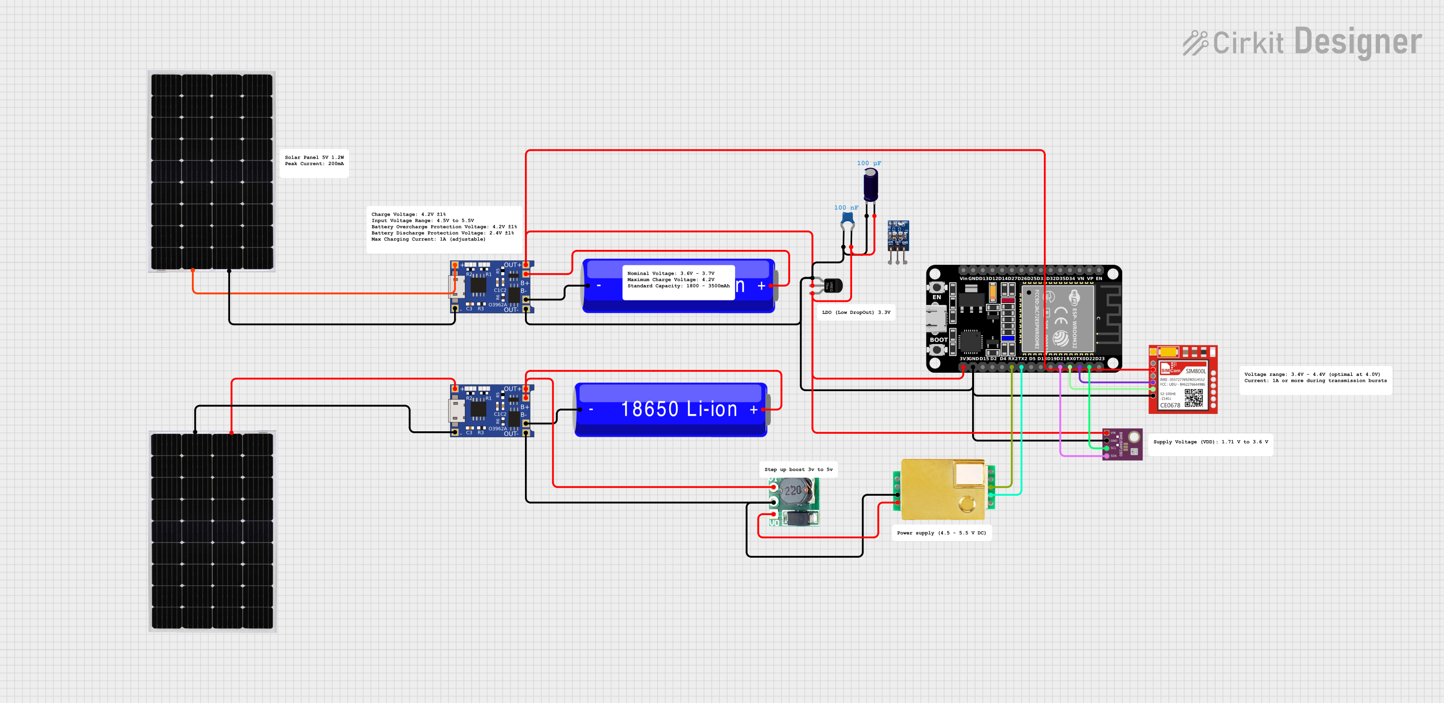
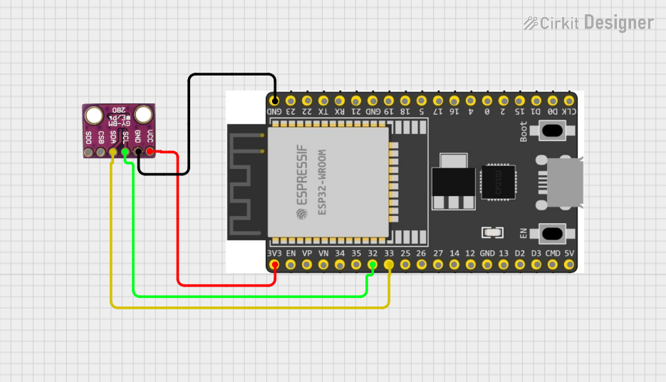
Connecting the GY-BME280 to an Arduino UNO (I2C Mode)

  1. Wiring: Connect the module to the Arduino UNO as follows:

    • VIN → 3.3V pin on the Arduino
    • GND → GND pin on the Arduino
    • SCL → A5 (I2C clock line on Arduino UNO)
    • SDA → A4 (I2C data line on Arduino UNO)
    • Leave CS and SDO unconnected for I2C mode.
  2. Install Required Libraries:

    • Install the Adafruit BME280 library and its dependency, Adafruit Sensor, from the Arduino Library Manager.
  3. Upload Example Code: Use the following code to read temperature, humidity, and pressure data from the sensor:

    #include <Wire.h>
    #include <Adafruit_Sensor.h>
    #include <Adafruit_BME280.h>
    
    // Create an instance of the BME280 sensor
    Adafruit_BME280 bme;
    
    void setup() {
      Serial.begin(9600);
      while (!Serial); // Wait for the serial monitor to open
    
      // Initialize the BME280 sensor
      if (!bme.begin(0x76)) { 
        // 0x76 is the default I2C address for the GY-BME280
        Serial.println("Could not find a valid BME280 sensor, check wiring!");
        while (1);
      }
    }
    
    void loop() {
      // Read and print temperature, humidity, and pressure
      Serial.print("Temperature = ");
      Serial.print(bme.readTemperature());
      Serial.println(" °C");
    
      Serial.print("Humidity = ");
      Serial.print(bme.readHumidity());
      Serial.println(" %");
    
      Serial.print("Pressure = ");
      Serial.print(bme.readPressure() / 100.0F); // Convert Pa to hPa
      Serial.println(" hPa");
    
      Serial.println();
      delay(2000); // Wait 2 seconds before the next reading
    }
    

Important Considerations

  • Voltage Compatibility: The GY-BME280 operates at 3.3V. Do not connect it directly to 5V systems without a level shifter.
  • I2C Address: The default I2C address is 0x76. If there are address conflicts, you can change it to 0x77 by pulling the SDO pin high.
  • Pull-Up Resistors: The module includes onboard pull-up resistors for I2C lines. If you experience communication issues, ensure no additional pull-ups are interfering.

Troubleshooting and FAQs

Common Issues

  1. Sensor Not Detected:

    • Cause: Incorrect wiring or I2C address mismatch.
    • Solution: Double-check the connections and ensure the correct I2C address (0x76 or 0x77) is used in the code.
  2. Incorrect Readings:

    • Cause: Environmental factors such as condensation or rapid temperature changes.
    • Solution: Place the sensor in a stable environment and avoid exposing it to water or extreme conditions.
  3. Communication Errors:

    • Cause: Voltage mismatch or loose connections.
    • Solution: Ensure the module is powered with 3.3V and all connections are secure.

FAQs

Q1: Can I use the GY-BME280 with a 5V microcontroller?
A1: Yes, but you must use a logic level shifter to convert the 5V signals to 3.3V to avoid damaging the sensor.

Q2: How do I switch between I2C and SPI modes?
A2: For I2C mode, leave the CS pin unconnected. For SPI mode, connect the CS pin to the appropriate control signal and configure the SDO pin.

Q3: What is the maximum cable length for I2C communication?
A3: The maximum length depends on the pull-up resistor values and the I2C clock speed. For most applications, keep the cable length under 1 meter to ensure reliable communication.

By following this documentation, you can effectively integrate the GY-BME280 3V3 into your projects and troubleshoot common issues with ease.