How to Use Micro PD Board - Top: Examples, Pinouts, and Specs
Introduction
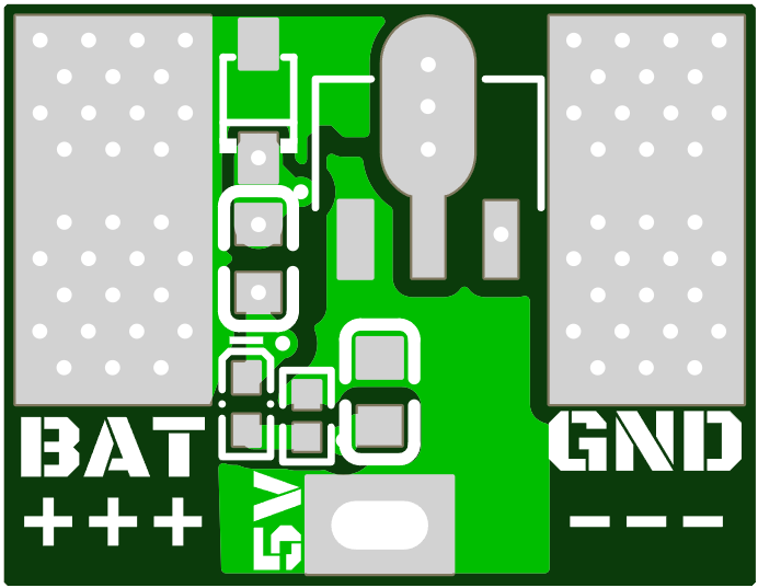
The Micro PD Board - Top by Just 'Cuz Robotics is a compact and efficient printed circuit board (PCB) designed for Power Delivery (PD) applications. It facilitates seamless power management and distribution in electronic devices, making it an essential component for projects requiring reliable and efficient power handling. Its small form factor and robust design make it ideal for use in robotics, IoT devices, and other compact electronic systems.
Explore Projects Built with Micro PD Board - Top


Explore Projects Built with Micro PD Board - Top
Common Applications and Use Cases
- Power distribution in robotics and automation systems
- IoT devices requiring efficient power management
- Battery-powered systems with multiple voltage requirements
- Prototyping and development of compact electronic devices
- Power delivery in drones and other portable electronics
Technical Specifications
The following table outlines the key technical specifications of the Micro PD Board - Top:
| Specification | Details |
|---|---|
| Manufacturer | Just 'Cuz Robotics |
| Part ID | JUST CUZ ROBOTICS MICRO POWER DISTRIBUTION BOARD |
| Input Voltage Range | 5V to 20V DC |
| Output Voltage Options | 3.3V, 5V, 12V |
| Maximum Output Current | 3A per output channel |
| Dimensions | 25mm x 25mm |
| Operating Temperature | -20°C to 85°C |
| PCB Layers | 2-layer design |
| Connector Type | Screw terminals and JST connectors |
| Protection Features | Overcurrent, overvoltage, and thermal shutdown |
Pin Configuration and Descriptions
The Micro PD Board - Top features multiple input and output pins for flexible power distribution. The table below describes the pin configuration:
| Pin Name | Type | Description |
|---|---|---|
| VIN | Power Input | Main power input (5V to 20V DC). |
| GND | Ground | Common ground for the circuit. |
| VOUT1 | Power Output | Regulated output voltage (selectable: 3.3V/5V/12V). |
| VOUT2 | Power Output | Regulated output voltage (selectable: 3.3V/5V/12V). |
| SEL1 | Control Input | Voltage selection pin for VOUT1. |
| SEL2 | Control Input | Voltage selection pin for VOUT2. |
| EN | Control Input | Enable pin to turn the board on/off. |
Usage Instructions
How to Use the Component in a Circuit
- Power Input: Connect the input voltage (5V to 20V DC) to the
VINpin and the ground to theGNDpin. - Voltage Selection: Use the
SEL1andSEL2pins to select the desired output voltage forVOUT1andVOUT2. Refer to the manufacturer's datasheet for the specific logic levels required for voltage selection. - Power Outputs: Connect your load to the
VOUT1and/orVOUT2pins. Ensure the total current draw does not exceed 3A per channel. - Enable Pin: Use the
ENpin to enable or disable the board. Pull the pin high to enable the board and low to disable it. - Mounting: Secure the board in your project using screws or adhesive, ensuring proper ventilation for heat dissipation.
Important Considerations and Best Practices
- Input Voltage: Ensure the input voltage is within the specified range (5V to 20V DC) to avoid damaging the board.
- Current Limits: Do not exceed the maximum output current of 3A per channel to prevent overheating or triggering the overcurrent protection.
- Heat Management: If operating at high currents, ensure adequate ventilation or use a heatsink to manage heat dissipation.
- Voltage Selection: Double-check the voltage selection logic before powering the board to avoid incorrect output voltages.
- Polarity: Always connect the input voltage with the correct polarity to prevent damage to the board.
Example: Using with an Arduino UNO
The Micro PD Board - Top can be used to power an Arduino UNO and other peripherals. Below is an example circuit and code:
Circuit Setup
- Connect the
VINpin of the Micro PD Board to a 12V DC power supply. - Connect the
GNDpin of the Micro PD Board to the ground of the Arduino UNO. - Connect the
VOUT1pin (set to 5V) to the5Vpin of the Arduino UNO. - Use the
ENpin to control the power delivery to the Arduino UNO.
Arduino Code Example
// Example code to control the EN pin of the Micro PD Board
// This code toggles the power delivery on and off every 2 seconds.

const int enablePin = 7; // Connect EN pin of Micro PD Board to Arduino pin 7

void setup() {
  pinMode(enablePin, OUTPUT); // Set the EN pin as an output
}

void loop() {
  digitalWrite(enablePin, HIGH); // Enable power delivery
  delay(2000); // Wait for 2 seconds
  digitalWrite(enablePin, LOW); // Disable power delivery
  delay(2000); // Wait for 2 seconds
}
Troubleshooting and FAQs
Common Issues and Solutions
No Output Voltage:
- Cause: The
ENpin is not pulled high. - Solution: Ensure the
ENpin is connected to a high logic level to enable the board.
- Cause: The
Overheating:
- Cause: Excessive current draw or insufficient ventilation.
- Solution: Reduce the load current or improve ventilation around the board.
Incorrect Output Voltage:
- Cause: Incorrect voltage selection on
SEL1orSEL2. - Solution: Verify the logic levels on the selection pins and adjust as needed.
- Cause: Incorrect voltage selection on
Board Not Powering On:
- Cause: Input voltage is out of range or connected with incorrect polarity.
- Solution: Check the input voltage and polarity, ensuring it is within the specified range.
FAQs
Q1: Can I use the Micro PD Board to power multiple devices simultaneously?
A1: Yes, you can use both VOUT1 and VOUT2 to power multiple devices, provided the total current draw does not exceed 3A per channel.
Q2: What happens if I exceed the maximum current rating?
A2: The board's overcurrent protection will activate, shutting down the output to prevent damage.
Q3: Can I use the board in outdoor applications?
A3: The board is not weatherproof. If used outdoors, ensure it is enclosed in a weather-resistant case.
Q4: How do I select the output voltage?
A4: Use the SEL1 and SEL2 pins to select the desired output voltage. Refer to the datasheet for the specific logic levels required.
This concludes the documentation for the Micro PD Board - Top. For further assistance, refer to the manufacturer's datasheet or contact Just 'Cuz Robotics support.