How to Use ESP32 Shield: Examples, Pinouts, and Specs
Introduction
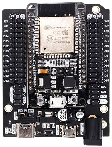
The ESP32 Shield is a versatile development board that integrates the ESP32 microcontroller, offering built-in Wi-Fi and Bluetooth capabilities. It is designed to simplify the development of IoT (Internet of Things) applications, wireless communication projects, and smart devices. The shield provides a variety of GPIO (General Purpose Input/Output) pins, making it easy to interface with sensors, actuators, and other electronic components.
Explore Projects Built with ESP32 Shield
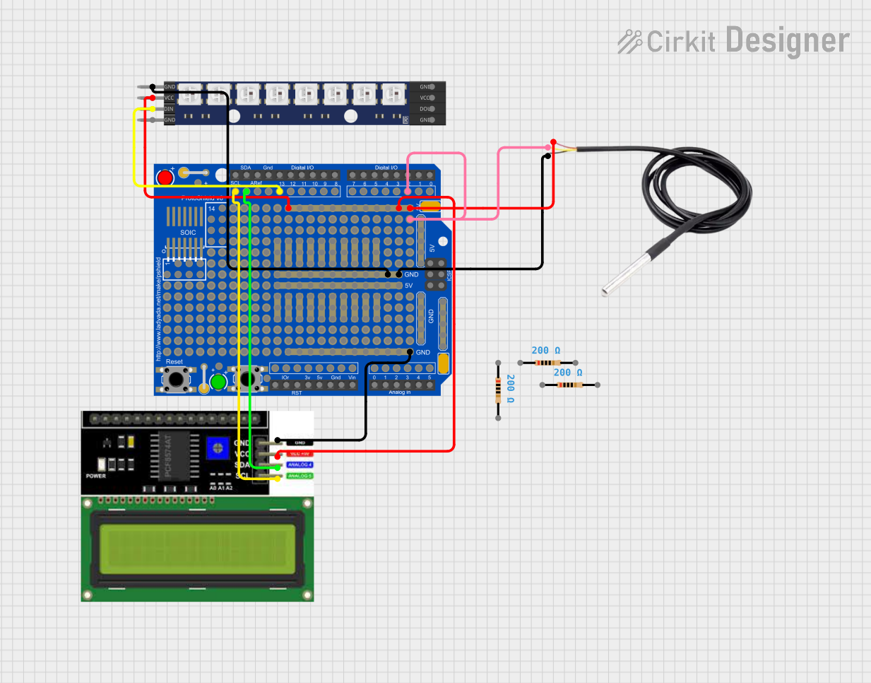
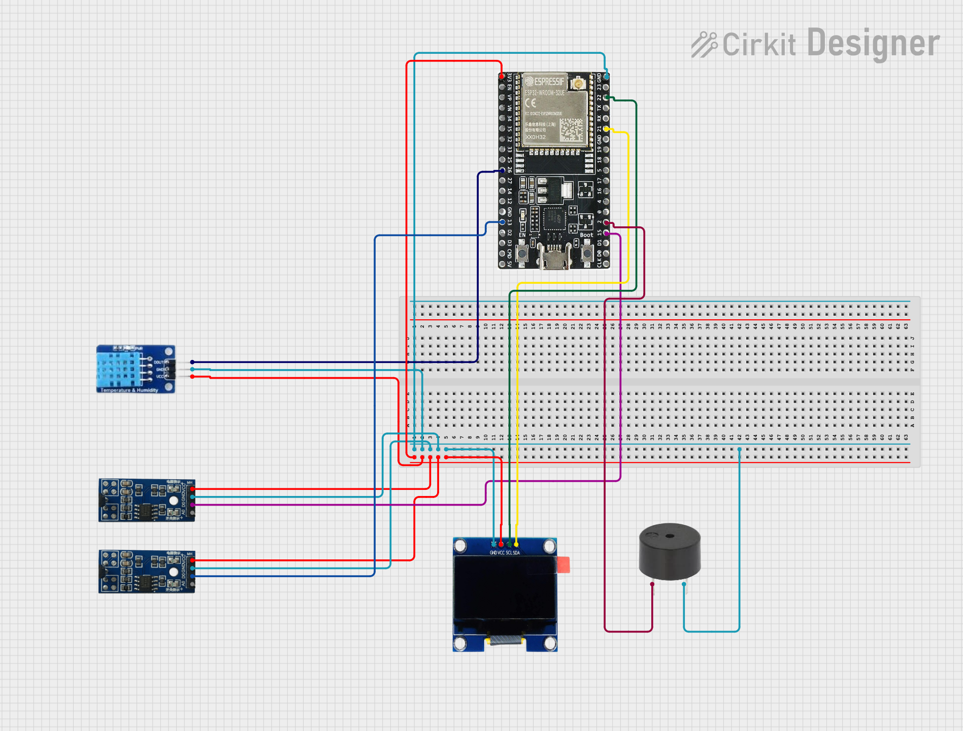


Explore Projects Built with ESP32 Shield
Common Applications and Use Cases
- IoT devices and smart home automation
- Wireless data logging and monitoring
- Remote control systems
- Bluetooth-enabled devices
- Prototyping and development of embedded systems
Technical Specifications
The ESP32 Shield is built around the ESP32 microcontroller, which features dual-core processing and integrated wireless communication modules. Below are the key technical details:
Key Technical Details
| Parameter | Specification |
|---|---|
| Microcontroller | ESP32 |
| Wireless Connectivity | Wi-Fi 802.11 b/g/n, Bluetooth 4.2 |
| Operating Voltage | 3.3V |
| Input Voltage (VIN) | 5V (via USB or external power supply) |
| GPIO Pins | 30+ (varies by shield design) |
| Flash Memory | 4MB (typical) |
| Clock Speed | Up to 240 MHz |
| Power Consumption | ~160 mA (active), ~10 µA (deep sleep) |
| Communication Interfaces | UART, SPI, I2C, PWM, ADC, DAC |
| ADC Resolution | 12-bit |
| DAC Resolution | 8-bit |
| Operating Temperature | -40°C to 85°C |
Pin Configuration and Descriptions
The ESP32 Shield typically includes a variety of pins for interfacing with external components. Below is a general pinout description:
| Pin Name | Description |
|---|---|
| VIN | Input voltage (5V) for powering the shield |
| GND | Ground connection |
| 3V3 | 3.3V output for powering external components |
| GPIOx | General-purpose input/output pins (x = pin number) |
| ADCx | Analog-to-digital converter pins (x = channel number) |
| DACx | Digital-to-analog converter pins (x = channel number) |
| TX / RX | UART communication pins for serial data transmission and reception |
| SCL / SDA | I2C communication pins for clock and data |
| MOSI / MISO | SPI communication pins for data transfer |
| EN | Enable pin to reset or wake the ESP32 |
| BOOT | Boot mode selection pin (used for flashing firmware) |
Note: The exact pin configuration may vary depending on the specific ESP32 Shield model. Always refer to the manufacturer's datasheet for precise details.
Usage Instructions
How to Use the ESP32 Shield in a Circuit
- Powering the Shield: Connect the VIN pin to a 5V power source or use a USB cable to power the shield.
- Connecting to Peripherals: Use the GPIO pins to interface with sensors, actuators, or other components. Ensure the voltage levels are compatible (3.3V logic).
- Programming the ESP32: Use the Arduino IDE or ESP-IDF (Espressif IoT Development Framework) to write and upload code to the ESP32. Connect the shield to your computer via USB for programming.
- Wireless Communication: Configure the Wi-Fi or Bluetooth settings in your code to enable wireless functionality.
Important Considerations and Best Practices
- Voltage Levels: The ESP32 operates at 3.3V logic. Avoid connecting 5V signals directly to GPIO pins without level shifting.
- Power Supply: Ensure a stable power supply to avoid unexpected resets or malfunctions.
- Pin Multiplexing: Some pins have multiple functions (e.g., ADC, DAC, UART). Check the datasheet to avoid conflicts.
- Deep Sleep Mode: Use deep sleep mode to reduce power consumption in battery-powered applications.
Example Code for Arduino UNO Integration
Below is an example of using the ESP32 Shield to connect to a Wi-Fi network and send data to a server:
#include <WiFi.h> // Include the Wi-Fi library

// Replace with your network credentials
const char* ssid = "Your_SSID";
const char* password = "Your_PASSWORD";

void setup() {
  Serial.begin(115200); // Initialize serial communication
  delay(1000);

  // Connect to Wi-Fi
  Serial.print("Connecting to Wi-Fi");
  WiFi.begin(ssid, password);
  while (WiFi.status() != WL_CONNECTED) {
    delay(500);
    Serial.print(".");
  }
  Serial.println("\nWi-Fi connected!");
  Serial.print("IP Address: ");
  Serial.println(WiFi.localIP()); // Print the assigned IP address
}

void loop() {
  // Add your main code here
  delay(1000);
}
Tip: Ensure the ESP32 Shield is properly connected to the Arduino UNO via UART or other communication interfaces.
Troubleshooting and FAQs
Common Issues and Solutions
ESP32 Shield Not Powering On
- Solution: Check the power supply voltage and ensure it is within the acceptable range (5V for VIN or USB).
Wi-Fi Connection Fails
- Solution: Verify the SSID and password in your code. Ensure the Wi-Fi network is active and within range.
GPIO Pins Not Responding
- Solution: Check for pin conflicts or incorrect pin assignments in your code. Ensure the connected components are functioning properly.
Code Upload Fails
- Solution: Ensure the correct COM port and board type are selected in the Arduino IDE. Press and hold the BOOT button during the upload process if necessary.
FAQs
Can the ESP32 Shield be powered by a battery? Yes, you can use a 3.7V LiPo battery with a suitable voltage regulator to power the shield.
Is the ESP32 Shield compatible with 5V logic? No, the ESP32 operates at 3.3V logic. Use level shifters for interfacing with 5V components.
How do I reset the ESP32 Shield? Press the EN (Enable) button to reset the ESP32 microcontroller.
Can I use the ESP32 Shield without Wi-Fi or Bluetooth? Yes, the ESP32 can function as a standalone microcontroller for non-wireless applications.
By following this documentation, you can effectively utilize the ESP32 Shield for a wide range of projects and applications.