How to Use Smart LED Control Board: Examples, Pinouts, and Specs
Introduction
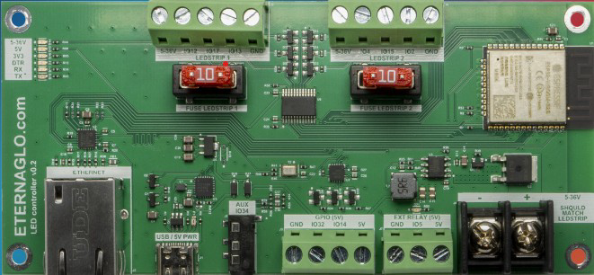
The Smart LED Control Board (Manufacturer: Eternalgo, Part ID: Plus) is a versatile and efficient control module designed to manage and operate LED lighting systems. It supports advanced features such as dimming, color changing, and remote control via smart devices, making it ideal for modern lighting applications. This board is compatible with a wide range of LED types and can be integrated into both residential and commercial lighting systems.
Explore Projects Built with Smart LED Control Board

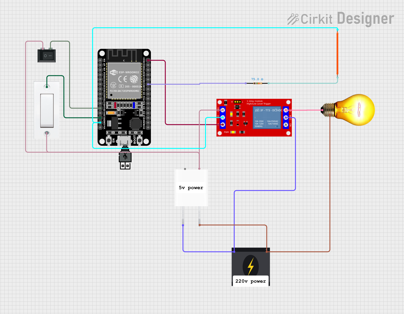

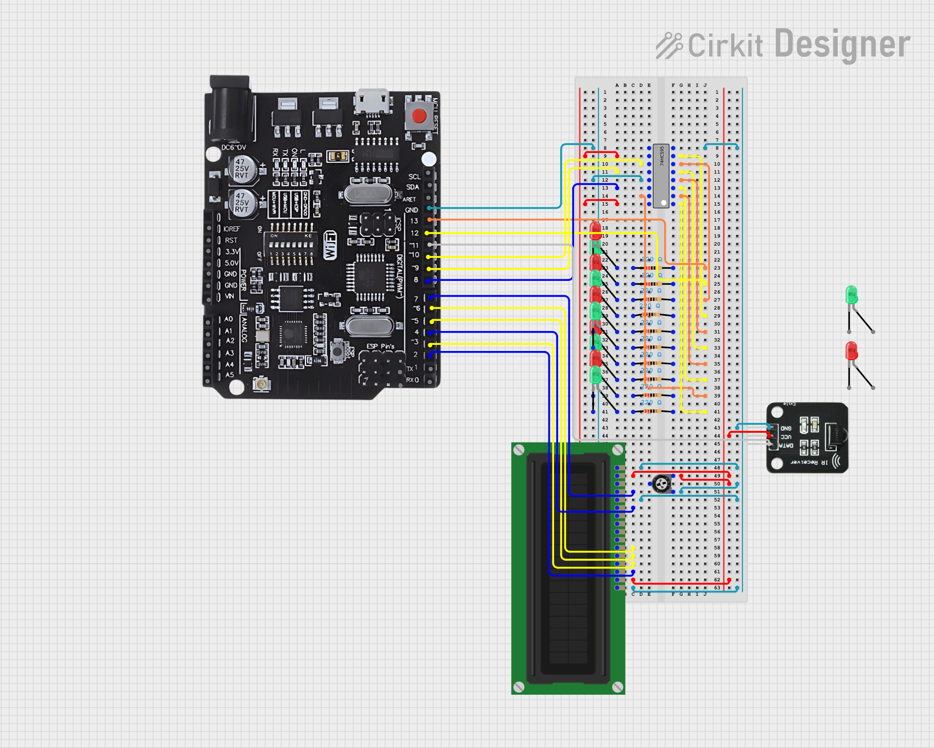
Explore Projects Built with Smart LED Control Board
Common Applications and Use Cases
- Smart home lighting systems with app-based control
- RGB and RGBW LED strip lighting for decorative purposes
- Commercial lighting installations requiring dimming and scheduling
- IoT-enabled lighting systems for remote operation
- Stage lighting and dynamic color effects
Technical Specifications
Key Technical Details
| Parameter | Specification |
|---|---|
| Input Voltage | 5V to 24V DC |
| Maximum Output Current | 10A (total across all channels) |
| Number of Channels | 4 (supports RGBW or 4 single-color LEDs) |
| Communication Protocol | Wi-Fi (2.4 GHz) and Bluetooth |
| Control Interface | Mobile app, voice assistant, or API |
| Dimming Range | 0% to 100% (PWM-based) |
| PWM Frequency | 1 kHz to 5 kHz (adjustable) |
| Operating Temperature | -20°C to 60°C |
| Dimensions | 50mm x 30mm x 10mm |
Pin Configuration and Descriptions
| Pin Name | Pin Type | Description |
|---|---|---|
| VIN | Power Input | Connect to a DC power source (5V to 24V). |
| GND | Ground | Common ground for power and signal connections. |
| CH1 | Output | PWM output for LED channel 1 (e.g., Red). |
| CH2 | Output | PWM output for LED channel 2 (e.g., Green). |
| CH3 | Output | PWM output for LED channel 3 (e.g., Blue). |
| CH4 | Output | PWM output for LED channel 4 (e.g., White). |
| RX | Input | UART receive pin for firmware updates or debugging. |
| TX | Output | UART transmit pin for firmware updates or debugging. |
| RESET | Input | Reset pin to restart the board. |
Usage Instructions
How to Use the Component in a Circuit
- Power Connection: Connect the VIN pin to a DC power source (5V to 24V) and the GND pin to the ground of the power supply.
- LED Connection: Connect the LED anodes to the CH1, CH2, CH3, and CH4 pins as needed. The cathodes of the LEDs should be connected to the GND pin.
- Control Setup: Use the Eternalgo mobile app or a compatible voice assistant to pair the board via Wi-Fi or Bluetooth. Follow the app instructions to configure the board.
- PWM Settings: Adjust the PWM frequency and dimming levels through the app or API to achieve the desired lighting effects.
Important Considerations and Best Practices
- Ensure the total current drawn by the LEDs does not exceed the 10A maximum output current.
- Use appropriate heat dissipation methods if operating at high currents for extended periods.
- Avoid connecting the board to a power supply that exceeds the 24V input voltage limit.
- For firmware updates, connect the RX and TX pins to a USB-to-UART adapter and use Eternalgo's firmware update tool.
- If using RGBW LEDs, ensure the wiring matches the channel assignments (e.g., CH1 = Red, CH2 = Green, etc.).
Arduino UNO Example Code
The Smart LED Control Board can be controlled via PWM signals from an Arduino UNO. Below is an example code snippet to control the brightness of an RGB LED strip:
// Define PWM pins for RGB channels
const int redPin = 9;   // Connect to CH1
const int greenPin = 10; // Connect to CH2
const int bluePin = 11;  // Connect to CH3

void setup() {
  // Set PWM pins as outputs
  pinMode(redPin, OUTPUT);
  pinMode(greenPin, OUTPUT);
  pinMode(bluePin, OUTPUT);
}

void loop() {
  // Example: Fade Red channel from 0 to 255
  for (int brightness = 0; brightness <= 255; brightness++) {
    analogWrite(redPin, brightness); // Set Red channel brightness
    delay(10); // Small delay for smooth fading
  }

  // Example: Fade Green channel from 0 to 255
  for (int brightness = 0; brightness <= 255; brightness++) {
    analogWrite(greenPin, brightness); // Set Green channel brightness
    delay(10);
  }

  // Example: Fade Blue channel from 0 to 255
  for (int brightness = 0; brightness <= 255; brightness++) {
    analogWrite(bluePin, brightness); // Set Blue channel brightness
    delay(10);
  }
}
Troubleshooting and FAQs
Common Issues and Solutions
LEDs Not Lighting Up:
- Cause: Incorrect wiring or insufficient power supply.
- Solution: Double-check the wiring connections and ensure the power supply meets the voltage and current requirements.
Board Not Connecting to Wi-Fi:
- Cause: Incorrect Wi-Fi credentials or unsupported network frequency.
- Solution: Ensure the Wi-Fi network is 2.4 GHz and re-enter the credentials in the app.
Flickering LEDs:
- Cause: Low PWM frequency or unstable power supply.
- Solution: Increase the PWM frequency via the app or use a stable power source.
Overheating:
- Cause: Excessive current draw or poor ventilation.
- Solution: Reduce the current load or improve heat dissipation with a heatsink or fan.
FAQs
Q: Can I control the board with a microcontroller other than Arduino?
A: Yes, any microcontroller capable of generating PWM signals can control the board.Q: Does the board support voice assistants like Alexa or Google Assistant?
A: Yes, the board is compatible with popular voice assistants for hands-free control.Q: Can I use the board with a 12V LED strip?
A: Yes, the board supports input voltages from 5V to 24V, making it compatible with 12V LED strips.Q: How do I reset the board to factory settings?
A: Press and hold the RESET pin for 5 seconds to restore factory settings.
This documentation provides all the necessary details to get started with the Smart LED Control Board and troubleshoot common issues effectively.