How to Use DHT20: Examples, Pinouts, and Specs
Introduction
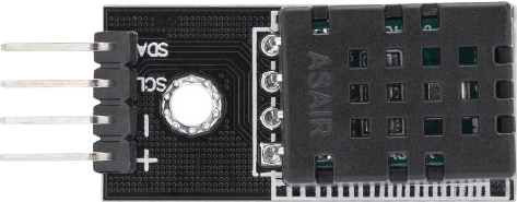
The DHT20, manufactured by AZ-Delivery, is a digital temperature and humidity sensor that provides accurate and reliable measurements. It uses a capacitive humidity sensor and a thermistor to measure the surrounding air and outputs a digital signal on the data pin. This sensor is widely used in various applications, including weather stations, HVAC systems, and environmental monitoring.
Explore Projects Built with DHT20
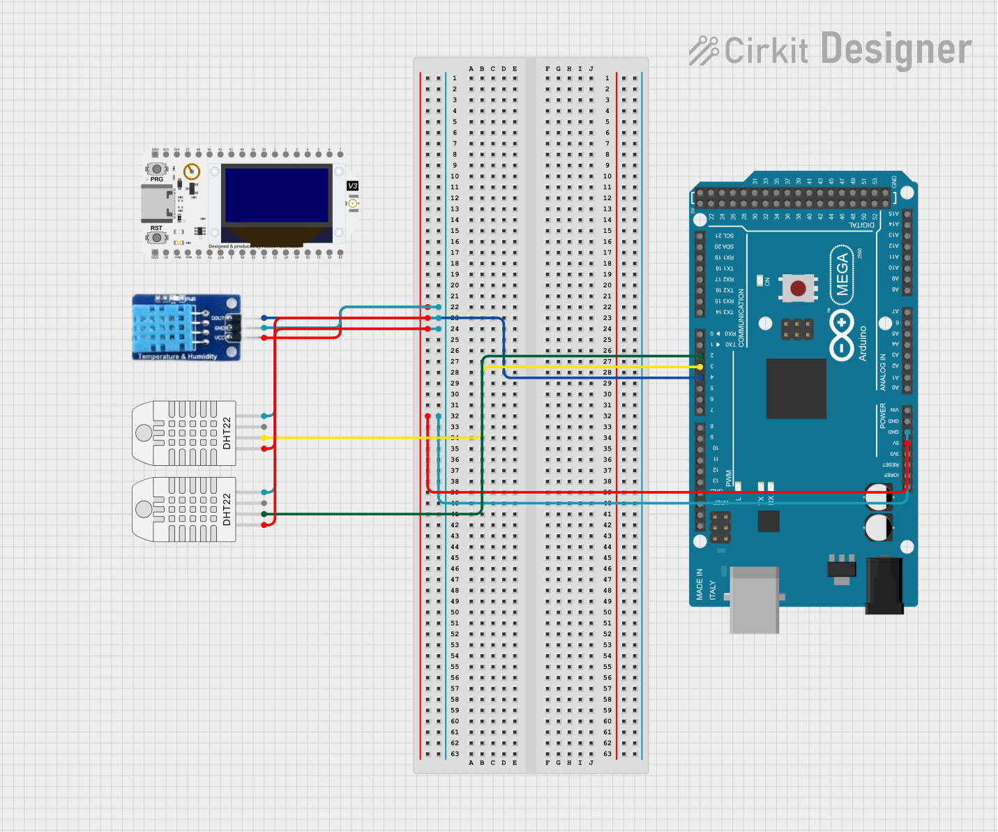
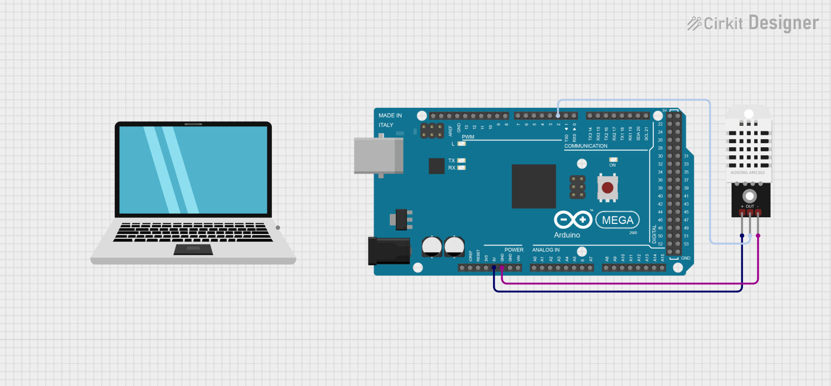
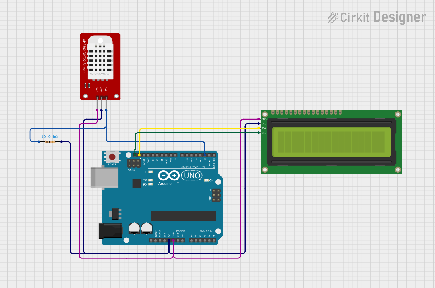
Explore Projects Built with DHT20
Technical Specifications
Key Technical Details
| Parameter | Value |
|---|---|
| Operating Voltage | 3.3V to 5.5V |
| Operating Current | 0.3mA (measuring) |
| Temperature Range | -40°C to 80°C |
| Humidity Range | 0% to 100% RH |
| Temperature Accuracy | ±0.5°C |
| Humidity Accuracy | ±3% RH |
| Communication | I2C |
| Dimensions | 15mm x 10mm x 5mm |
Pin Configuration and Descriptions
| Pin Number | Pin Name | Description |
|---|---|---|
| 1 | VCC | Power supply (3.3V to 5.5V) |
| 2 | GND | Ground |
| 3 | SDA | Serial Data Line (I2C) |
| 4 | SCL | Serial Clock Line (I2C) |
Usage Instructions
How to Use the DHT20 in a Circuit
- Power Supply: Connect the VCC pin to a 3.3V or 5V power supply and the GND pin to the ground.
- I2C Communication: Connect the SDA pin to the SDA pin on your microcontroller and the SCL pin to the SCL pin on your microcontroller.
- Pull-up Resistors: Use 4.7kΩ pull-up resistors on the SDA and SCL lines if they are not already present on your microcontroller board.
Important Considerations and Best Practices
- Stable Power Supply: Ensure a stable power supply to avoid fluctuations that can affect sensor readings.
- Proper Placement: Place the sensor in a location where it can accurately measure the ambient temperature and humidity without interference.
- Avoid Condensation: Avoid placing the sensor in environments where condensation can occur, as this can damage the sensor.
Example Code for Arduino UNO
#include <Wire.h>
#include "DHT20.h"

DHT20 dht20;

void setup() {
  Serial.begin(9600);
  Wire.begin();
  dht20.begin();
}

void loop() {
  float temperature = dht20.readTemperature();
  float humidity = dht20.readHumidity();

  Serial.print("Temperature: ");
  Serial.print(temperature);
  Serial.println(" °C");

  Serial.print("Humidity: ");
  Serial.print(humidity);
  Serial.println(" %");

  delay(2000); // Wait for 2 seconds before the next reading
}
Troubleshooting and FAQs
Common Issues and Solutions
No Data Output:
- Solution: Check the wiring connections and ensure that the SDA and SCL lines are correctly connected. Verify that the pull-up resistors are in place.
Inaccurate Readings:
- Solution: Ensure that the sensor is placed in an environment free from rapid temperature changes or condensation. Verify that the power supply is stable.
Sensor Not Detected:
- Solution: Ensure that the I2C address of the sensor matches the address used in the code. Check for any loose connections or damaged wires.
FAQs
Q1: Can the DHT20 be used with a 3.3V microcontroller?
- A1: Yes, the DHT20 can operate with a power supply ranging from 3.3V to 5.5V.
Q2: What is the maximum distance for the I2C communication?
- A2: The maximum distance for reliable I2C communication is typically around 1 meter. For longer distances, consider using I2C bus extenders.
Q3: How often should I take readings from the DHT20?
- A3: It is recommended to take readings at intervals of at least 2 seconds to allow the sensor to stabilize.
By following this documentation, users can effectively integrate the DHT20 sensor into their projects, ensuring accurate and reliable temperature and humidity measurements.