
How to Use ILI9341_2.4_parallel_8bit_TFT: Examples, Pinouts, and Specs
 Design with ILI9341_2.4_parallel_8bit_TFT in Cirkit Designer
Introduction
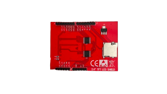
The ILI9341_2.4_parallel_8bit_TFT is a 2.4-inch TFT display module powered by the ILI9341 driver. It features an 8-bit parallel interface for fast communication, making it ideal for applications requiring vibrant graphics and text rendering. This display module is widely used in embedded systems, IoT devices, and DIY electronics projects due to its compact size, high resolution, and ease of integration.
Explore Projects Built with ILI9341_2.4_parallel_8bit_TFT
 Open Project in Cirkit Designer
 Open Project in Cirkit Designer
 Open Project in Cirkit Designer
 Open Project in Cirkit Designer
Explore Projects Built with ILI9341_2.4_parallel_8bit_TFT
Open Project in Cirkit DesignerOpen Project in Cirkit DesignerOpen Project in Cirkit DesignerOpen Project in Cirkit DesignerCommon Applications:
- Graphical user interfaces (GUIs) for embedded systems
- IoT dashboards and control panels
- Portable devices and handheld instruments
- Educational and hobbyist projects
- Real-time data visualization
Technical Specifications
Key Technical Details:
| Parameter | Value |
|---|---|
| Display Type | TFT LCD |
| Driver IC | ILI9341 |
| Screen Size | 2.4 inches |
| Resolution | 240 x 320 pixels (QVGA) |
| Interface | 8-bit parallel |
| Operating Voltage | 3.3V (logic level) |
| Backlight Voltage | 3.3V to 5V |
| Current Consumption | ~50mA (with backlight on) |
| Viewing Angle | ~160° |
| Color Depth | 65K (16-bit RGB 5-6-5 format) |
| Operating Temperature | -20°C to 70°C |
Pin Configuration:
The ILI9341_2.4_parallel_8bit_TFT module typically has a 16-pin interface. Below is the pinout description:
| Pin No. | Name | Description |
|---|---|---|
| 1 | GND | Ground |
| 2 | VCC | Power supply (3.3V or 5V for backlight) |
| 3 | CS | Chip Select (active low) |
| 4 | RESET | Reset pin (active low) |
| 5 | DC/RS | Data/Command control pin |
| 6 | WR | Write strobe (active low) |
| 7 | RD | Read strobe (active low) |
| 8-15 | D0-D7 | Data bus (8-bit parallel data lines) |
| 16 | LED_A | Backlight anode (connect to 3.3V or 5V via a resistor) |
Usage Instructions
Connecting the Display to a Microcontroller:
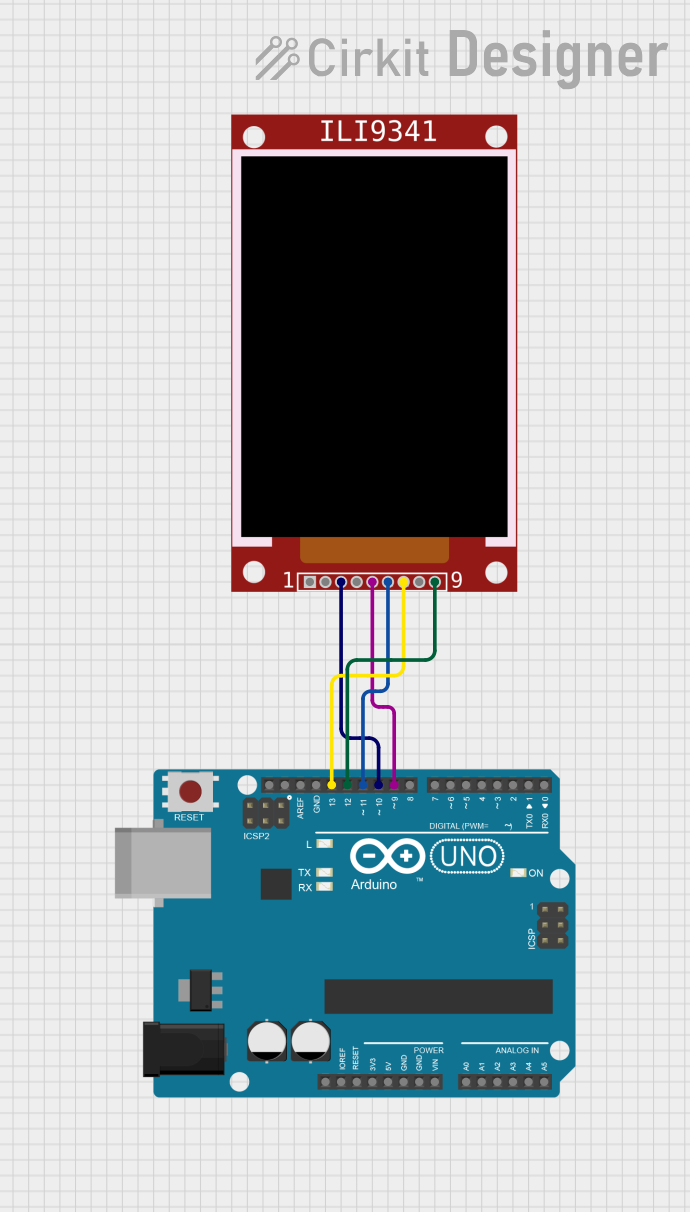
To use the ILI9341_2.4_parallel_8bit_TFT with a microcontroller like the Arduino UNO, follow these steps:
- Power Supply: Connect the
VCCpin to 3.3V or 5V (depending on the module's backlight requirements) andGNDto ground. - Data Lines: Connect the
D0-D7pins to the microcontroller's digital I/O pins. - Control Pins:
- Connect
CS,RESET,DC/RS,WR, andRDto separate digital I/O pins. - Ensure proper pin mapping in your code.
- Connect
- Backlight: Connect the
LED_Apin to 3.3V or 5V through a current-limiting resistor (e.g., 220Ω).
Example Code for Arduino UNO:
Below is an example of how to initialize and use the display with the Arduino UNO using the Adafruit_GFX and Adafruit_ILI9341 libraries:
#include <Adafruit_GFX.h>      // Core graphics library
#include <Adafruit_ILI9341.h>  // ILI9341 driver library

// Define pin connections
#define TFT_CS   10  // Chip Select pin
#define TFT_DC   9   // Data/Command pin
#define TFT_RST  8   // Reset pin
#define TFT_WR   7   // Write pin
#define TFT_RD   6   // Read pin
#define TFT_D0   2   // Data pin D0 (D0-D7 connected sequentially)

// Create an instance of the display
Adafruit_ILI9341 tft = Adafruit_ILI9341(TFT_CS, TFT_DC, TFT_RST);

void setup() {
  // Initialize the display
  tft.begin();

  // Set rotation (0-3)
  tft.setRotation(1);

  // Fill the screen with a color
  tft.fillScreen(ILI9341_BLUE);

  // Draw a rectangle
  tft.fillRect(50, 50, 100, 100, ILI9341_RED);

  // Display text
  tft.setTextColor(ILI9341_WHITE);
  tft.setTextSize(2);
  tft.setCursor(10, 10);
  tft.print("Hello, TFT!");
}

void loop() {
  // Add your code here for dynamic updates
}
Important Considerations:
- Voltage Levels: Ensure the logic voltage levels of your microcontroller match the display's requirements (3.3V). Use level shifters if necessary.
- Current Limiting: Use a resistor for the backlight to prevent overcurrent damage.
- Library Compatibility: Use libraries like Adafruit_GFX and Adafruit_ILI9341 for simplified control.
Troubleshooting and FAQs
Common Issues:
Blank Screen:
- Verify power connections and ensure the backlight is on.
- Check the
RESETpin connection and ensure it is not floating. - Confirm that the
CS,DC/RS, andWRpins are correctly connected.
Incorrect Colors or Graphics:
- Ensure the data lines (
D0-D7) are properly connected and not swapped. - Verify that the display is initialized with the correct color format (16-bit RGB 5-6-5).
- Ensure the data lines (
Slow Performance:
- Use optimized libraries and ensure the microcontroller's clock speed is sufficient.
- Minimize unnecessary screen updates in your code.
No Response to Commands:
- Check the
CSpin to ensure it is pulled low during communication. - Verify that the
WRandRDpins are correctly toggled.
- Check the
FAQs:
Q: Can I use this display with a 5V microcontroller?
A: Yes, but you must use level shifters for the data and control lines to avoid damaging the display.
Q: How do I adjust the brightness of the backlight?
A: Use a PWM signal on the LED_A pin to control the brightness.
Q: Can I use this display in SPI mode?
A: No, this specific module is designed for an 8-bit parallel interface. For SPI, consider an ILI9341 module with SPI support.
Q: What is the maximum refresh rate of the display?
A: The refresh rate depends on the microcontroller's processing speed and the efficiency of the code. Typically, it can achieve ~30 FPS with optimized code.
By following this documentation, you can effectively integrate the ILI9341_2.4_parallel_8bit_TFT into your projects and troubleshoot common issues with ease.