
How to Use Inductors: Examples, Pinouts, and Specs
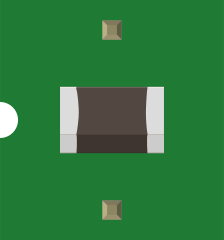
 Design with Inductors in Cirkit Designer
Introduction
Inductors are passive electrical components that store energy in a magnetic field when electric current flows through them. They are typically constructed as coils of wire and are characterized by their inductance, measured in henries (H). Inductors resist changes in current, making them essential in various electronic applications.
Explore Projects Built with Inductors
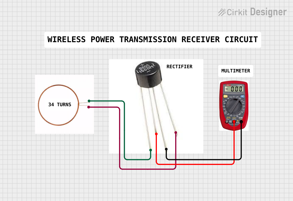 Open Project in Cirkit Designer
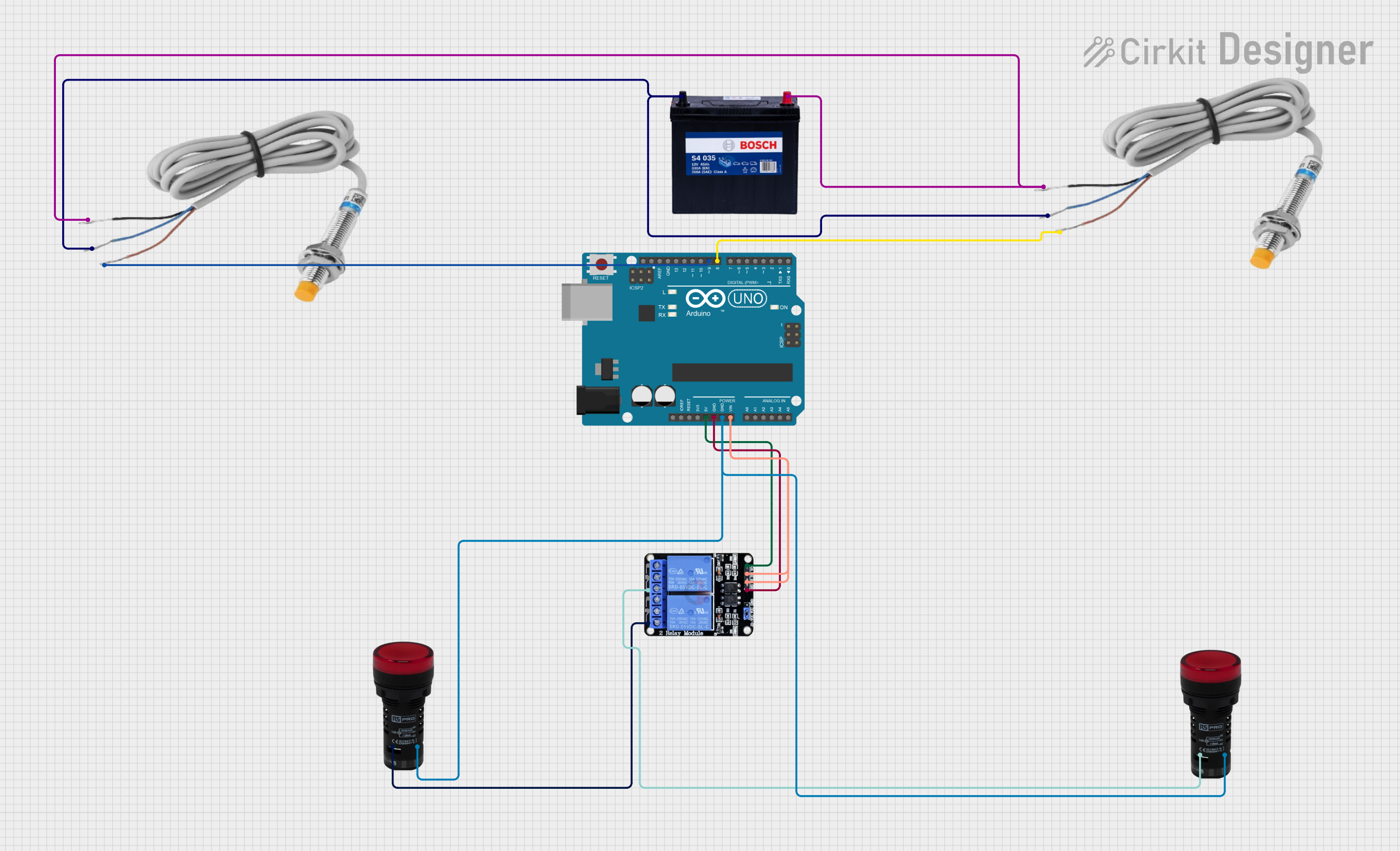 Open Project in Cirkit Designer
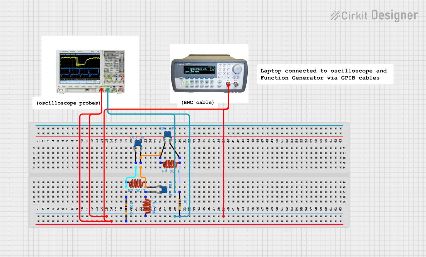 Open Project in Cirkit Designer
 Open Project in Cirkit Designer
Explore Projects Built with Inductors
Open Project in Cirkit DesignerOpen Project in Cirkit DesignerOpen Project in Cirkit DesignerOpen Project in Cirkit DesignerCommon Applications and Use Cases
- Filtering Applications: Used in power supplies and audio circuits to filter out unwanted noise or ripple.
- Energy Storage: Found in DC-DC converters and power management circuits.
- Tuning Circuits: Used in radio frequency (RF) circuits for tuning and signal selection.
- Transformers: Inductors are a key component in transformer design for voltage conversion.
- Chokes: Used to block high-frequency AC signals while allowing DC or low-frequency signals to pass.
Technical Specifications
Key Technical Details
- Inductance Range: Typically from nanohenries (nH) to henries (H).
- Current Rating: Maximum current the inductor can handle without overheating.
- DC Resistance (DCR): The resistance of the wire used in the inductor, measured in ohms (Ω).
- Saturation Current: The current at which the inductor's core material saturates, reducing its inductance.
- Self-Resonant Frequency (SRF): The frequency at which the inductor's parasitic capacitance resonates with its inductance.
Pin Configuration and Descriptions
Inductors are generally two-terminal components. Below is a table describing the terminals:
| Pin | Description |
|---|---|
| Pin 1 | Input terminal for current flow. |
| Pin 2 | Output terminal for current flow. |
For surface-mount inductors, the pins are typically labeled as A and B or may not have explicit markings. Ensure correct orientation based on circuit design.
Usage Instructions
How to Use the Component in a Circuit
- Determine the Required Inductance: Calculate the inductance value needed for your application using formulas or circuit simulation tools.
- Select an Appropriate Inductor: Choose an inductor with the correct inductance, current rating, and SRF for your circuit.
- Connect the Inductor: Place the inductor in series or parallel as required by the circuit design. For example:
- In a low-pass filter, connect the inductor in series with the load.
- In a DC-DC converter, use the inductor as part of the energy storage and transfer mechanism.
- Verify Orientation: While inductors are not polarized, ensure proper placement to avoid mechanical stress or interference with nearby components.
- Test the Circuit: Measure the circuit's performance to ensure the inductor is functioning as expected.
Important Considerations and Best Practices
- Avoid Core Saturation: Ensure the current through the inductor does not exceed its saturation current rating.
- Minimize Parasitics: Use shielded inductors or proper PCB layout techniques to reduce electromagnetic interference (EMI).
- Thermal Management: Monitor the inductor's temperature to prevent overheating, especially in high-current applications.
- Frequency Response: Ensure the inductor operates below its self-resonant frequency for optimal performance.
Example: Using an Inductor with an Arduino UNO
Inductors are often used in conjunction with microcontrollers like the Arduino UNO for tasks such as filtering or energy storage. Below is an example of using an inductor in a simple low-pass filter to smooth a PWM signal:
Circuit Description
- The Arduino generates a PWM signal on pin 9.
- The inductor (e.g., 100 µH) and a capacitor (e.g., 10 µF) form a low-pass filter to convert the PWM signal into a smooth DC voltage.
Code Example
// Arduino code to generate a PWM signal on pin 9
// This PWM signal can be smoothed using an inductor-capacitor filter

void setup() {
  pinMode(9, OUTPUT); // Set pin 9 as an output
}

void loop() {
  analogWrite(9, 128); // Generate a 50% duty cycle PWM signal
  // Adjust the value (0-255) to change the output voltage
}
Troubleshooting and FAQs
Common Issues Users Might Face
Inductor Overheating:
- Cause: Exceeding the current rating or poor thermal management.
- Solution: Use an inductor with a higher current rating or improve cooling.
Unexpected Noise or EMI:
- Cause: Parasitic effects or improper PCB layout.
- Solution: Use shielded inductors and follow good PCB design practices.
Circuit Not Functioning as Expected:
- Cause: Incorrect inductance value or poor component selection.
- Solution: Verify the inductor's specifications and ensure it matches the circuit requirements.
Core Saturation:
- Cause: Current exceeds the saturation current rating.
- Solution: Use an inductor with a higher saturation current rating.
Solutions and Tips for Troubleshooting
- Measure Inductance: Use an LCR meter to verify the inductor's inductance.
- Check Connections: Ensure the inductor is properly soldered or connected in the circuit.
- Inspect for Damage: Look for signs of physical damage, such as burnt or cracked cores.
- Simulate the Circuit: Use simulation software to verify the circuit design before implementation.
By following these guidelines, you can effectively use inductors in your electronic projects and troubleshoot any issues that arise.