Cirkit Designer Logo
Cirkit Designer
Your all-in-one circuit design IDE
Home / 
Component Documentation

How to Use ESP32: Examples, Pinouts, and Specs

Image of ESP32
Cirkit Designer LogoDesign with ESP32 in Cirkit Designer

Introduction

The ESP32 is a low-cost, low-power system on a chip (SoC) developed by Espressif Systems. It features integrated Wi-Fi and Bluetooth capabilities, making it an ideal choice for Internet of Things (IoT) applications, smart devices, and embedded systems. With its dual-core processor, extensive GPIO options, and support for various communication protocols, the ESP32 is a versatile and powerful microcontroller for a wide range of projects.

Explore Projects Built with ESP32

Use Cirkit Designer to design, explore, and prototype these projects online. Some projects support real-time simulation. Click "Open Project" to start designing instantly!
ESP32-Based Sensor Monitoring System with OLED Display and E-Stop
Image of MVP_design: A project utilizing ESP32 in a practical application
This circuit features an ESP32 microcontroller that interfaces with a variety of sensors and output devices. It is powered by a Lipo battery through a buck converter, ensuring a stable voltage supply. The ESP32 collects data from a DHT11 temperature and humidity sensor and a vibration sensor, controls a buzzer, and displays information on an OLED screen. An emergency stop (E Stop) is connected for safety purposes, allowing the system to be quickly deactivated.
Cirkit Designer LogoOpen Project in Cirkit Designer
ESP32-Based NTP Clock with DHT22 Temperature Sensor and WS2812 LED Matrix Display
Image of date time and temperature display : A project utilizing ESP32 in a practical application
This circuit features an ESP32 Devkit V1 microcontroller connected to a DHT22 temperature and humidity sensor and an 8x8 WS2812 RGB LED matrix. The ESP32 reads temperature data from the DHT22 sensor and displays the current date, time, and temperature on the LED matrix, with date and time synchronized via NTP (Network Time Protocol). The ESP32 provides power to both the DHT22 and the LED matrix and communicates with the DHT22 via GPIO 4 and with the LED matrix via GPIO 5.
Cirkit Designer LogoOpen Project in Cirkit Designer
ESP32-Based Environmental Monitoring System with Water Flow Sensing
Image of Water: A project utilizing ESP32 in a practical application
This circuit features an ESP32 Devkit V1 microcontroller connected to a DHT22 temperature and humidity sensor and a water flow sensor. The ESP32 reads environmental data from the DHT22 via a digital input pin (D33) and monitors water flow through the water flow sensor connected to another digital input pin (D23). The ESP32 is powered through its VIN pin, and both sensors are powered by the ESP32's 3V3 output, with common ground connections.
Cirkit Designer LogoOpen Project in Cirkit Designer
ESP32-Based Smart Weather Station with Wi-Fi Connectivity
Image of flowchart 3D: A project utilizing ESP32 in a practical application
This circuit features an ESP32 microcontroller interfacing with various sensors and modules, including a DHT22 temperature and humidity sensor, an ESP32 CAM for image capture, an I2C LCD screen for display, a load cell with an HX711 interface for weight measurement, and a buzzer for audio alerts. The ESP32 handles data acquisition, processing, and communication with these peripherals to create a multi-functional monitoring and alert system.
Cirkit Designer LogoOpen Project in Cirkit Designer

Explore Projects Built with ESP32

Use Cirkit Designer to design, explore, and prototype these projects online. Some projects support real-time simulation. Click "Open Project" to start designing instantly!
Image of MVP_design: A project utilizing ESP32 in a practical application
ESP32-Based Sensor Monitoring System with OLED Display and E-Stop
This circuit features an ESP32 microcontroller that interfaces with a variety of sensors and output devices. It is powered by a Lipo battery through a buck converter, ensuring a stable voltage supply. The ESP32 collects data from a DHT11 temperature and humidity sensor and a vibration sensor, controls a buzzer, and displays information on an OLED screen. An emergency stop (E Stop) is connected for safety purposes, allowing the system to be quickly deactivated.
Cirkit Designer LogoOpen Project in Cirkit Designer
Image of date time and temperature display : A project utilizing ESP32 in a practical application
ESP32-Based NTP Clock with DHT22 Temperature Sensor and WS2812 LED Matrix Display
This circuit features an ESP32 Devkit V1 microcontroller connected to a DHT22 temperature and humidity sensor and an 8x8 WS2812 RGB LED matrix. The ESP32 reads temperature data from the DHT22 sensor and displays the current date, time, and temperature on the LED matrix, with date and time synchronized via NTP (Network Time Protocol). The ESP32 provides power to both the DHT22 and the LED matrix and communicates with the DHT22 via GPIO 4 and with the LED matrix via GPIO 5.
Cirkit Designer LogoOpen Project in Cirkit Designer
Image of Water: A project utilizing ESP32 in a practical application
ESP32-Based Environmental Monitoring System with Water Flow Sensing
This circuit features an ESP32 Devkit V1 microcontroller connected to a DHT22 temperature and humidity sensor and a water flow sensor. The ESP32 reads environmental data from the DHT22 via a digital input pin (D33) and monitors water flow through the water flow sensor connected to another digital input pin (D23). The ESP32 is powered through its VIN pin, and both sensors are powered by the ESP32's 3V3 output, with common ground connections.
Cirkit Designer LogoOpen Project in Cirkit Designer
Image of flowchart 3D: A project utilizing ESP32 in a practical application
ESP32-Based Smart Weather Station with Wi-Fi Connectivity
This circuit features an ESP32 microcontroller interfacing with various sensors and modules, including a DHT22 temperature and humidity sensor, an ESP32 CAM for image capture, an I2C LCD screen for display, a load cell with an HX711 interface for weight measurement, and a buzzer for audio alerts. The ESP32 handles data acquisition, processing, and communication with these peripherals to create a multi-functional monitoring and alert system.
Cirkit Designer LogoOpen Project in Cirkit Designer

Common Applications and Use Cases

  • IoT devices and smart home automation
  • Wireless sensor networks
  • Wearable electronics
  • Industrial automation
  • Robotics and drones
  • Real-time data monitoring and logging

Technical Specifications

The ESP32 is packed with features that make it suitable for both simple and complex applications. Below are its key technical specifications:

Key Features

  • Processor: Dual-core Xtensa® 32-bit LX6 microprocessor, up to 240 MHz
  • Memory: 520 KB SRAM, 4 MB Flash (varies by model)
  • Wireless Connectivity:
    • Wi-Fi: 802.11 b/g/n
    • Bluetooth: v4.2 BR/EDR and BLE
  • Operating Voltage: 3.0V to 3.6V
  • GPIO Pins: 34 programmable GPIOs
  • Communication Protocols: UART, SPI, I2C, I2S, CAN, PWM
  • ADC/DAC: 12-bit ADC (up to 18 channels), 2x 8-bit DAC
  • Power Consumption: Ultra-low power consumption with multiple power modes
  • Operating Temperature: -40°C to +125°C

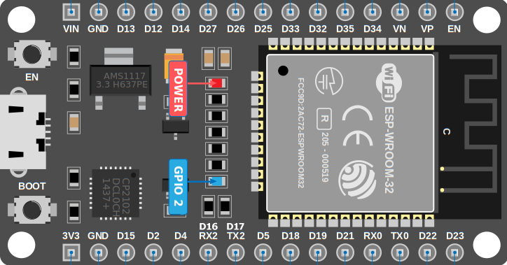
Pin Configuration and Descriptions

The ESP32 has a variety of pins for different functionalities. Below is a summary of the pin configuration:

Pin Name Function Description
GPIO0 Input/Output, Boot Mode Select Used for boot mode selection during startup.
GPIO1 (TXD0) UART TX UART0 transmit pin.
GPIO3 (RXD0) UART RX UART0 receive pin.
GPIO12-15 Input/Output, ADC, PWM General-purpose pins with ADC and PWM capabilities.
GPIO16-19 Input/Output, SPI SPI interface pins for communication with peripherals.
GPIO21 I2C SDA Data line for I2C communication.
GPIO22 I2C SCL Clock line for I2C communication.
GPIO25-27 Input/Output, DAC, ADC General-purpose pins with DAC and ADC functionality.
EN Enable Chip enable pin. Pulling low disables the chip.
3V3 Power 3.3V power supply input.
GND Ground Ground connection.

Note: The exact pinout may vary depending on the ESP32 module or development board (e.g., ESP32-WROOM-32, ESP32-WROVER).

Usage Instructions

The ESP32 can be used in a variety of circuits and applications. Below are the steps to get started and important considerations:

Getting Started with ESP32

  1. Power the ESP32: Connect the 3.3V and GND pins to a suitable power source.
  2. Connect to a Computer: Use a USB cable to connect the ESP32 development board to your computer.
  3. Install Drivers: Install the necessary USB-to-serial drivers (e.g., CP2102 or CH340) if required.
  4. Set Up the IDE: Use the Arduino IDE or Espressif's ESP-IDF for programming the ESP32.
    • For Arduino IDE:
      • Install the ESP32 board package via the Board Manager.
      • Select the appropriate ESP32 board and port under the Tools menu.
  5. Write and Upload Code: Write your program and upload it to the ESP32 using the IDE.

Example: Blinking an LED with ESP32

Here is a simple example of how to blink an LED connected to GPIO2 of the ESP32:

// Define the GPIO pin where the LED is connected
const int ledPin = 2;

void setup() {
  // Set the LED pin as an output
  pinMode(ledPin, OUTPUT);
}

void loop() {
  // Turn the LED on
  digitalWrite(ledPin, HIGH);
  delay(1000); // Wait for 1 second

  // Turn the LED off
  digitalWrite(ledPin, LOW);
  delay(1000); // Wait for 1 second
}

Important Considerations

  • Voltage Levels: Ensure all connected peripherals operate at 3.3V logic levels to avoid damaging the ESP32.
  • Boot Mode: Avoid pulling GPIO0, GPIO2, or GPIO15 to the wrong state during boot, as this may interfere with the boot process.
  • Power Supply: Use a stable power source to prevent unexpected resets or malfunctions.
  • Wi-Fi Interference: Place the ESP32 away from sources of interference for optimal Wi-Fi performance.

Troubleshooting and FAQs

Common Issues and Solutions

  1. ESP32 Not Detected by Computer

    • Ensure the correct USB drivers are installed (e.g., CP2102 or CH340).
    • Try a different USB cable or port.
  2. Code Upload Fails

    • Check that the correct board and port are selected in the IDE.
    • Hold the "BOOT" button on the ESP32 while uploading the code.
  3. Wi-Fi Connection Issues

    • Verify the SSID and password in your code.
    • Ensure the router is within range and not blocking the ESP32.
  4. Random Resets

    • Check the power supply for stability.
    • Avoid excessive current draw from GPIO pins.

FAQs

Q: Can the ESP32 operate on 5V?
A: No, the ESP32 operates at 3.3V. Applying 5V to GPIO pins can damage the chip.

Q: How do I reset the ESP32?
A: Press the "EN" (Enable) button on the development board to reset the ESP32.

Q: Can I use the ESP32 with Arduino libraries?
A: Yes, the ESP32 is compatible with many Arduino libraries, but some may require modifications.

Q: How do I reduce power consumption?
A: Use the ESP32's deep sleep mode to significantly reduce power consumption in battery-powered applications.

By following this documentation, you can effectively use the ESP32 in your projects and troubleshoot common issues.