Cirkit Designer
Your all-in-one circuit design IDE
Home /
Component Documentation
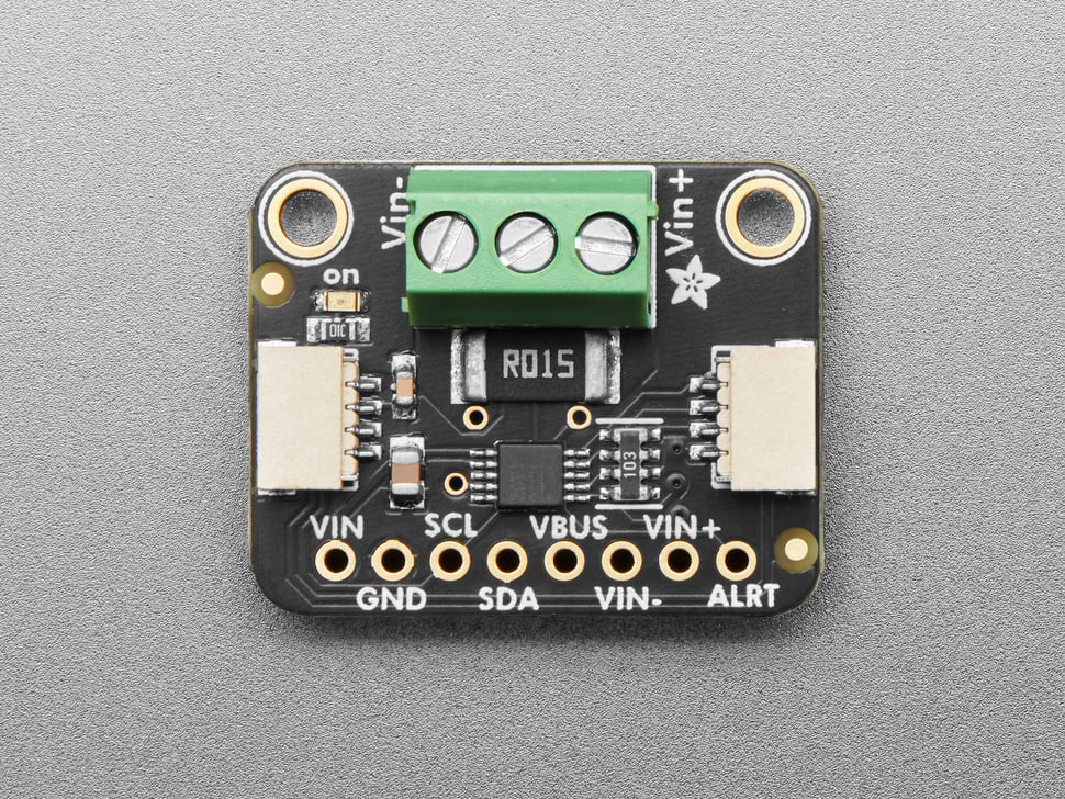
How to Use Adafruit INA228: Examples, Pinouts, and Specs
Introduction
The Adafruit INA228 is a high-precision, low-drift current sensor capable of measuring current, voltage, and power. It is designed for applications requiring accurate power monitoring and energy metering. This versatile sensor is ideal for use in battery-operated devices, power management systems, and energy monitoring applications.
Explore Projects Built with Adafruit INA228
Arduino Mega 2560 and INA219 Sensor for Current and Voltage Measurement
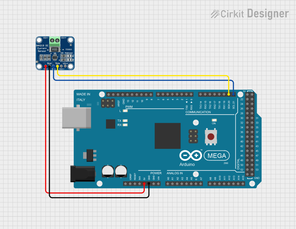
This circuit connects an Arduino Mega 2560 to an INA219 sensor for current and voltage measurement. The INA219 sensor communicates with the Arduino via the I2C protocol, and the Arduino reads and prints the current, bus voltage, shunt voltage, and power values to the Serial Monitor.
Arduino UNO Based Precision Battery Monitoring System with INA228 and LM4040
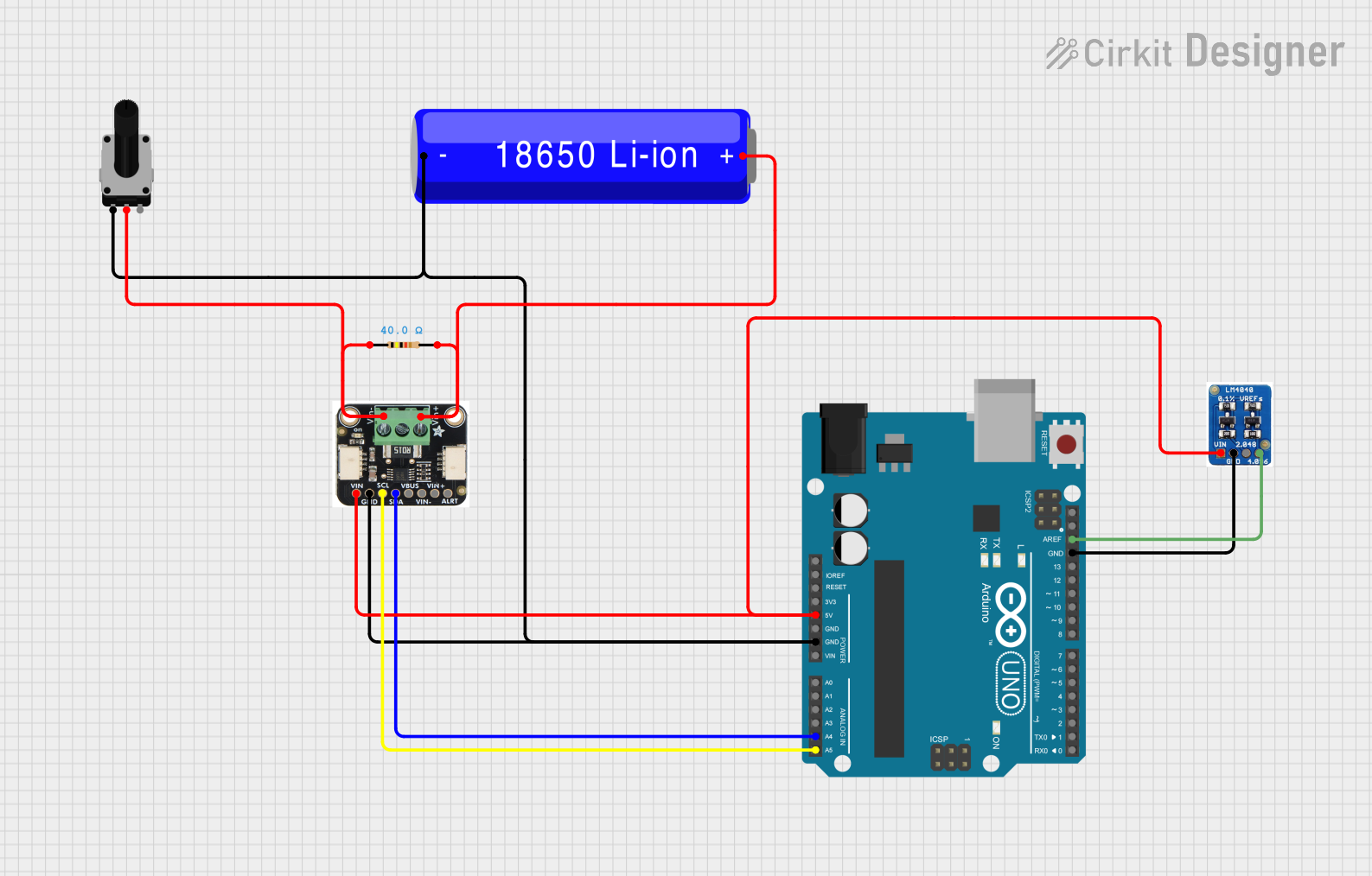
This circuit is designed to monitor and measure current, voltage, and power using an INA228 sensor interfaced with an Arduino UNO via I2C. The LM4040 provides a precise voltage reference for the Arduino's ADC, and a rotary potentiometer along with a series resistor and Li-ion battery setup enables variable voltage input for monitoring purposes.
Multi-Sensor Monitoring System with INA219, Hall Sensor, and OLED Display
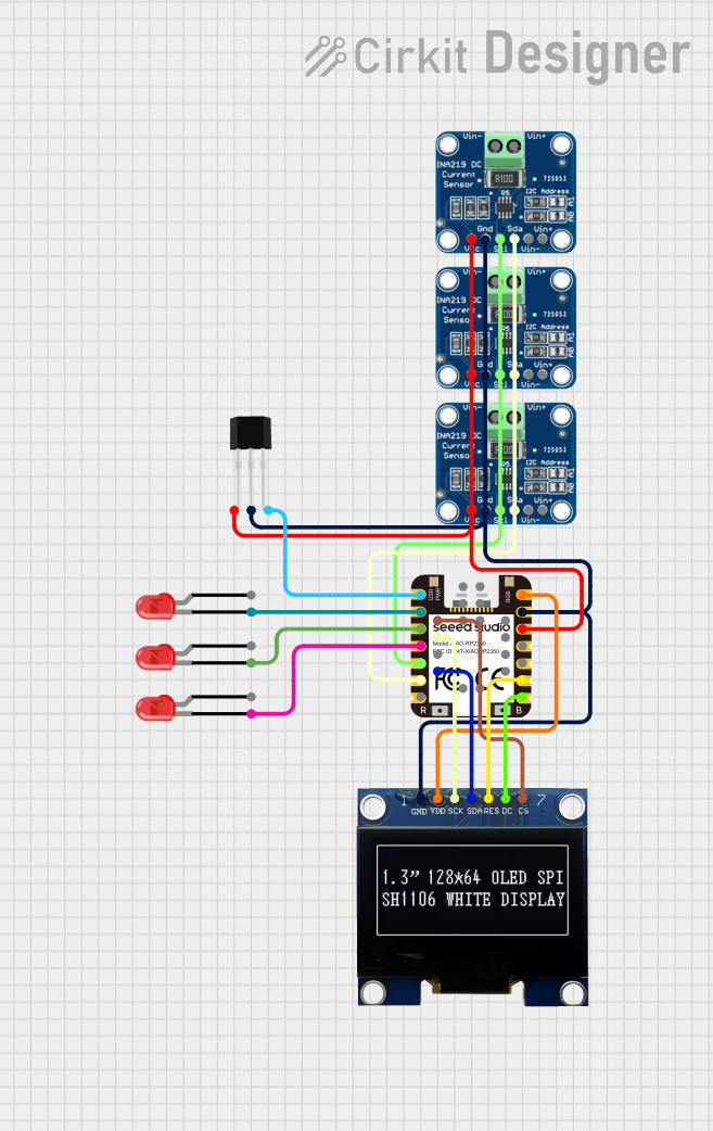
This circuit is designed for monitoring and displaying sensor data. It includes three INA219 current sensors, a GH1248 Hall sensor, and an SSD1306 OLED display, all interfaced with a Seeed Studio RP2350 microcontroller. The microcontroller reads data from the sensors and controls the display and three LEDs.
Arduino UNO-Based Smart Relay Control with INA219 Current Sensor and RGB LED
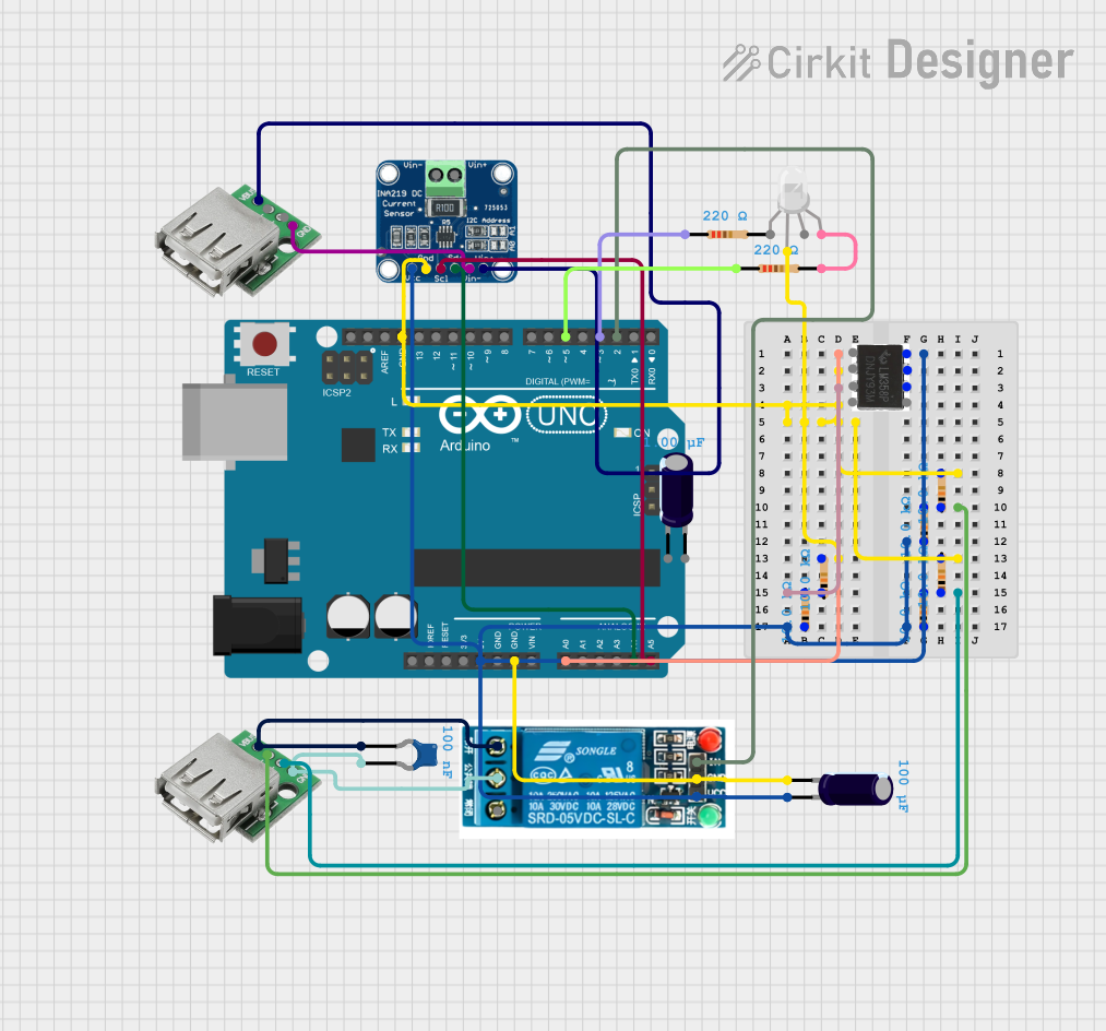
This circuit features an Arduino UNO microcontroller interfaced with an INA219 current sensor, a 5V relay, and an RGB LED. The Arduino reads current measurements from the INA219 via I2C and controls the relay and LED, potentially for monitoring and controlling power to a USB-connected device.
Explore Projects Built with Adafruit INA228
Arduino Mega 2560 and INA219 Sensor for Current and Voltage Measurement
This circuit connects an Arduino Mega 2560 to an INA219 sensor for current and voltage measurement. The INA219 sensor communicates with the Arduino via the I2C protocol, and the Arduino reads and prints the current, bus voltage, shunt voltage, and power values to the Serial Monitor.
Arduino UNO Based Precision Battery Monitoring System with INA228 and LM4040
This circuit is designed to monitor and measure current, voltage, and power using an INA228 sensor interfaced with an Arduino UNO via I2C. The LM4040 provides a precise voltage reference for the Arduino's ADC, and a rotary potentiometer along with a series resistor and Li-ion battery setup enables variable voltage input for monitoring purposes.
Multi-Sensor Monitoring System with INA219, Hall Sensor, and OLED Display
This circuit is designed for monitoring and displaying sensor data. It includes three INA219 current sensors, a GH1248 Hall sensor, and an SSD1306 OLED display, all interfaced with a Seeed Studio RP2350 microcontroller. The microcontroller reads data from the sensors and controls the display and three LEDs.
Arduino UNO-Based Smart Relay Control with INA219 Current Sensor and RGB LED
This circuit features an Arduino UNO microcontroller interfaced with an INA219 current sensor, a 5V relay, and an RGB LED. The Arduino reads current measurements from the INA219 via I2C and controls the relay and LED, potentially for monitoring and controlling power to a USB-connected device.
Technical Specifications
Key Technical Details
| Parameter | Value |
|---|---|
| Supply Voltage | 2.7V to 5.5V |
| Current Range | ±10A |
| Voltage Range | 0V to 36V |
| Power Consumption | 1.1mA (typical) |
| Communication | I2C |
| Resolution | 20-bit |
| Operating Temperature | -40°C to +125°C |
Pin Configuration and Descriptions
| Pin | Name | Description |
|---|---|---|
| 1 | VCC | Power supply (2.7V to 5.5V) |
| 2 | GND | Ground |
| 3 | SCL | I2C clock line |
| 4 | SDA | I2C data line |
| 5 | ALERT | Alert output (open-drain) |
| 6 | ADDR | I2C address selection |
| 7 | IN+ | Positive input for current measurement |
| 8 | IN- | Negative input for current measurement |
Usage Instructions
How to Use the Component in a Circuit
- Power Supply: Connect the VCC pin to a 2.7V to 5.5V power supply and the GND pin to the ground.
- I2C Communication: Connect the SCL and SDA pins to the corresponding I2C lines on your microcontroller.
- Current Measurement: Connect the IN+ and IN- pins in series with the load you want to measure.
- Address Selection: Use the ADDR pin to set the I2C address. This can be done by connecting it to VCC, GND, or leaving it floating.
- Alert Output: The ALERT pin can be used to trigger an interrupt on your microcontroller when a certain condition is met (e.g., overcurrent).
Important Considerations and Best Practices
- Bypass Capacitor: Place a 0.1µF bypass capacitor close to the VCC pin to filter out noise.
- Shunt Resistor: Use a precise shunt resistor for accurate current measurements.
- I2C Pull-up Resistors: Ensure that the I2C lines have appropriate pull-up resistors (typically 4.7kΩ).
- Thermal Management: Ensure proper thermal management to avoid overheating, especially in high-current applications.
Example Code for Arduino UNO
Below is an example code to interface the Adafruit INA228 with an Arduino UNO using the I2C protocol.
#include <Wire.h>
#include <Adafruit_INA228.h>

// Create an instance of the INA228 class
Adafruit_INA228 ina228;

void setup() {
  Serial.begin(9600);
  // Initialize I2C communication
  Wire.begin();

  // Initialize the INA228 sensor
  if (!ina228.begin()) {
    Serial.println("Failed to find INA228 chip");
    while (1) { delay(10); }
  }
  Serial.println("INA228 Found!");
}

void loop() {
  // Read current, voltage, and power
  float current = ina228.readCurrent();
  float voltage = ina228.readBusVoltage();
  float power = ina228.readPower();

  // Print the values to the Serial Monitor
  Serial.print("Current: "); Serial.print(current); Serial.println(" A");
  Serial.print("Voltage: "); Serial.print(voltage); Serial.println(" V");
  Serial.print("Power: "); Serial.print(power); Serial.println(" W");

  delay(1000); // Wait for 1 second before the next reading
}
Troubleshooting and FAQs
Common Issues Users Might Face
No Communication with the Sensor:
- Solution: Check the I2C connections and ensure the correct I2C address is used. Verify that the pull-up resistors are in place.
Incorrect Readings:
- Solution: Ensure that the shunt resistor is of the correct value and precision. Verify that the connections are secure and there is no noise interference.
Overheating:
- Solution: Ensure proper thermal management and avoid exceeding the maximum current rating.
Solutions and Tips for Troubleshooting
- Check Connections: Ensure all connections are secure and correctly placed.
- Verify Power Supply: Ensure the power supply voltage is within the specified range.
- Use Proper Pull-up Resistors: Ensure the I2C lines have appropriate pull-up resistors.
- Consult the Datasheet: Refer to the Adafruit INA228 datasheet for detailed information and advanced configurations.
By following this documentation, users can effectively integrate the Adafruit INA228 into their projects, ensuring accurate and reliable current, voltage, and power measurements.