How to Use Adafruit LSM303AGR: Examples, Pinouts, and Specs
Introduction
The Adafruit LSM303AGR is a compact and versatile 6 Degrees of Freedom (6-DoF) sensor module that combines a 3-axis accelerometer and a 3-axis magnetometer. This sensor is ideal for applications requiring the measurement of both linear acceleration and magnetic fields in three dimensions. Common use cases include orientation detection, motion detection, and compass functionalities in devices such as drones, smartphones, and other portable electronics.
Explore Projects Built with Adafruit LSM303AGR
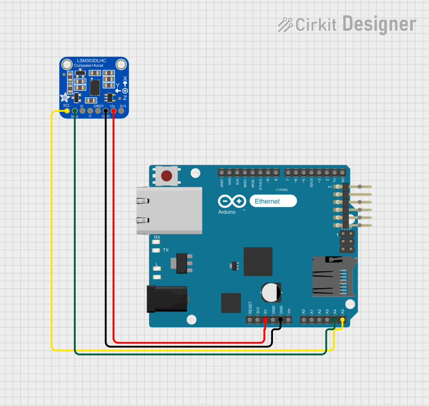
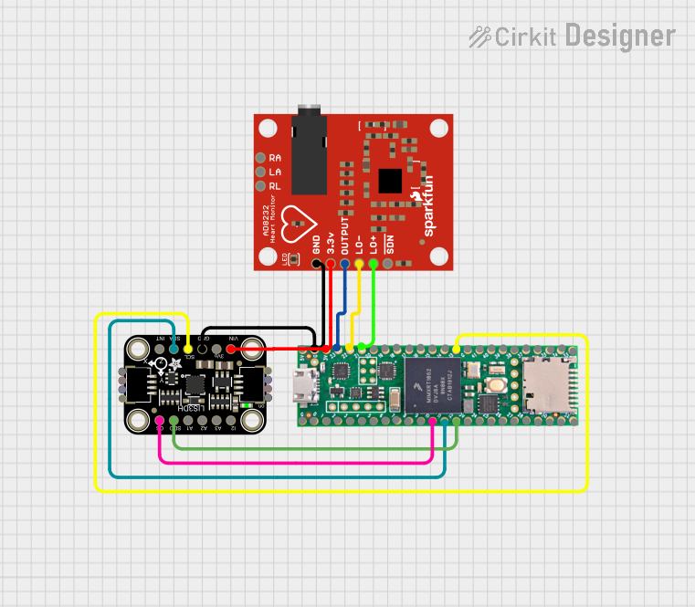
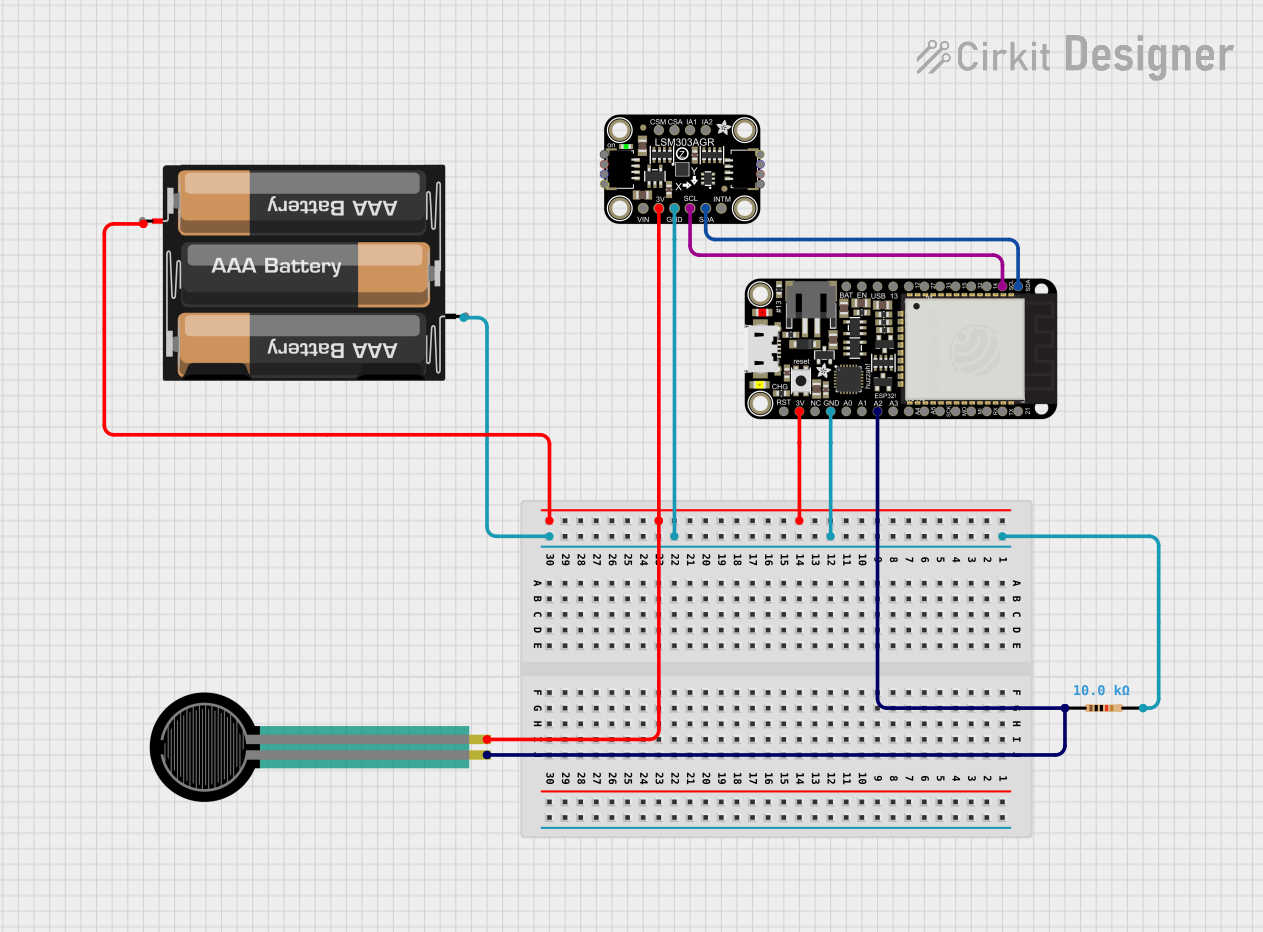
Explore Projects Built with Adafruit LSM303AGR
Technical Specifications
General Features
- 3-axis digital linear acceleration sensor
- 3-axis digital magnetic sensor
- Acceleration range: ±2/±4/±8/±16 g
- Magnetic range: ±50 gauss
- 16-bit data output
- I2C serial interface
- Operating Voltage: 2.5V to 5.5V
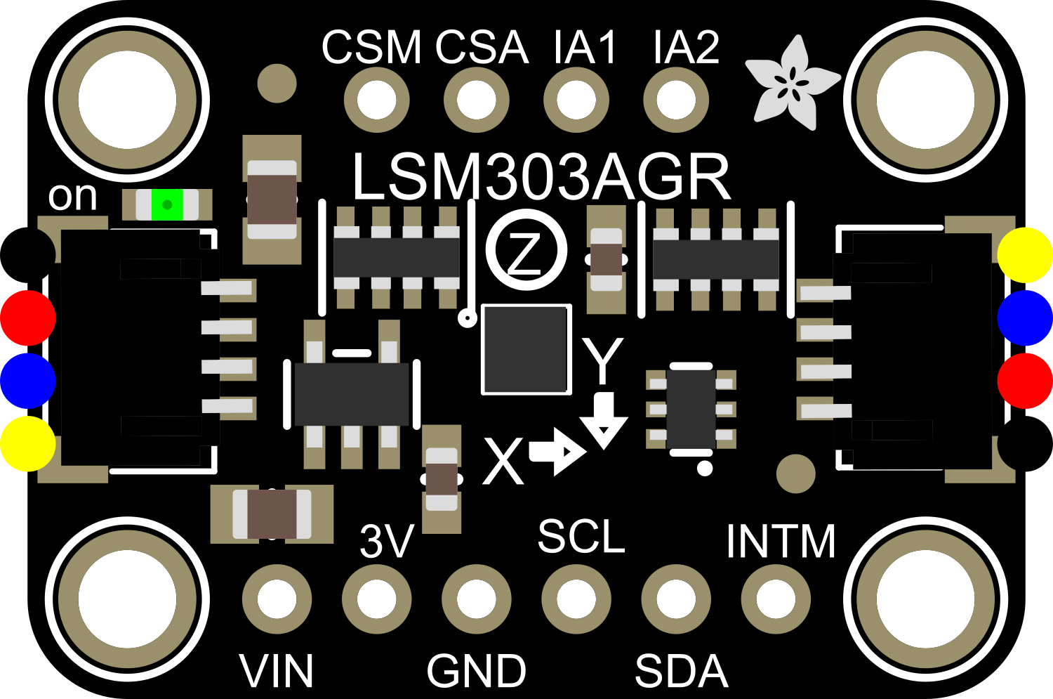
Pin Configuration and Descriptions
| Pin Number | Pin Name | Description |
|---|---|---|
| 1 | VIN | Power supply (2.5V to 5.5V) |
| 2 | 3Vo | 3.3V output from the voltage regulator |
| 3 | GND | Ground |
| 4 | SDA | I2C data line |
| 5 | SCL | I2C clock line |
| 6 | DRDY | Data ready output signal (optional) |
Usage Instructions
Integration with a Circuit
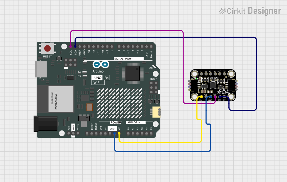
To use the LSM303AGR in a circuit, connect the VIN pin to a power supply between 2.5V and 5.5V, and the GND pin to the ground. The SDA and SCL pins should be connected to the I2C data and clock lines, respectively. If you wish to use the Data Ready (DRDY) feature, connect the DRDY pin to a digital input on your microcontroller.
Best Practices
- Ensure that the power supply is stable and within the specified voltage range.
- Use pull-up resistors on the I2C lines if they are not already present on the microcontroller board.
- Place the sensor away from magnetic fields that may interfere with the magnetometer readings.
- Calibrate the magnetometer in the application's environment for accurate readings.
Example Code for Arduino UNO
#include <Wire.h>
#include <Adafruit_Sensor.h>
#include <Adafruit_LSM303_U.h>

/* Create an instance of the LSM303 accelerometer and magnetometer sensor */
Adafruit_LSM303_Accel_Unified accel = Adafruit_LSM303_Accel_Unified(54321);
Adafruit_LSM303_Mag_Unified mag = Adafruit_LSM303_Mag_Unified(12345);

void setup(void) {
  Serial.begin(9600);
  Serial.println("LSM303AGR Test");

  /* Initialize the accelerometer */
  if (!accel.begin()) {
    Serial.println("No accelerometer detected");
    while (1);
  }

  /* Initialize the magnetometer */
  if (!mag.begin()) {
    Serial.println("No magnetometer detected");
    while (1);
  }
}

void loop(void) {
  /* Get a new sensor event */
  sensors_event_t event;

  /* Read the accelerometer */
  accel.getEvent(&event);
  Serial.print("X: "); Serial.print(event.acceleration.x); Serial.print(" ");
  Serial.print("Y: "); Serial.print(event.acceleration.y); Serial.print(" ");
  Serial.print("Z: "); Serial.print(event.acceleration.z); Serial.print(" m/s^2 ");
  Serial.println("");

  /* Read the magnetometer */
  mag.getEvent(&event);
  Serial.print("X: "); Serial.print(event.magnetic.x); Serial.print(" ");
  Serial.print("Y: "); Serial.print(event.magnetic.y); Serial.print(" ");
  Serial.print("Z: "); Serial.print(event.magnetic.z); Serial.print(" uT ");
  Serial.println("");

  /* Delay before the next reading */
  delay(500);
}
Troubleshooting and FAQs
Common Issues
- Sensor not detected: Ensure that the wiring is correct and that the sensor is properly powered.
- Inaccurate readings: Calibrate the sensor in your specific environment, as magnetic fields can vary.
- No data on I2C: Check for proper pull-up resistors and that no other device is conflicting on the I2C bus.
FAQs
Q: Can the LSM303AGR be used with a 3.3V system? A: Yes, the sensor can operate at 3.3V, and it includes a 3.3V regulator which can be used to power the sensor when supplied with higher voltages.
Q: How do I calibrate the magnetometer? A: Calibration typically involves rotating the sensor in several orientations and using software to determine and compensate for biases.
Q: What is the purpose of the DRDY pin? A: The Data Ready (DRDY) pin is an optional feature that signals when new data is available to read, which can be useful for synchronizing sensor readings.
For further assistance, consult the Adafruit LSM303AGR datasheet and the Adafruit Sensor library documentation.