Cirkit Designer Logo
Cirkit Designer
Your all-in-one circuit design IDE
Home / 
Component Documentation

How to Use MAX30102: Examples, Pinouts, and Specs

Image of MAX30102
Cirkit Designer LogoDesign with MAX30102 in Cirkit Designer

Introduction

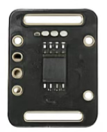
The MAX30102 is a pulse oximeter and heart-rate sensor module designed for non-invasive monitoring of vital signs. It utilizes photoplethysmography (PPG) technology to measure blood oxygen saturation (SpO2) and heart rate. The module integrates two LEDs (red and infrared), a photodetector, optical elements, and low-noise electronics with ambient light rejection, making it highly efficient and accurate for wearable and portable health monitoring devices.

Explore Projects Built with MAX30102

Use Cirkit Designer to design, explore, and prototype these projects online. Some projects support real-time simulation. Click "Open Project" to start designing instantly!
Battery-Powered Health Monitoring System with Nucleo WB55RG and OLED Display
Image of Pulsefex: A project utilizing MAX30102 in a practical application
This circuit is a multi-sensor data acquisition system that uses a Nucleo WB55RG microcontroller to interface with a digital temperature sensor (TMP102), a pulse oximeter and heart-rate sensor (MAX30102), and a 0.96" OLED display via I2C. Additionally, it includes a Sim800l module for GSM communication, powered by a 3.7V LiPo battery.
Cirkit Designer LogoOpen Project in Cirkit Designer
ESP32-Based Multi-Sensor Health Monitoring System with Bluetooth Connectivity
Image of circuit diagram: A project utilizing MAX30102 in a practical application
This circuit features an ESP32-WROOM-32UE microcontroller as the central processing unit, interfacing with a variety of sensors and modules. It includes a MAX30100 pulse oximeter and heart-rate sensor, an MLX90614 infrared thermometer, an HC-05 Bluetooth module for wireless communication, and a Neo 6M GPS module for location tracking. All components are powered by a common voltage supply and are connected to specific GPIO pins on the ESP32 for data exchange, with the sensors using I2C communication and the modules using UART.
Cirkit Designer LogoOpen Project in Cirkit Designer
ESP32 and MAX30100 Pulse Oximeter
Image of t: A project utilizing MAX30102 in a practical application
This circuit features an ESP32 microcontroller connected to a MAX30100 sensor, which is likely used for measuring pulse oximetry. The ESP32 is interfaced with the MAX30100 via I2C communication, as indicated by the SDA and SCL connections. Power is supplied to both the ESP32 and the MAX30100 by a 5V battery, with common ground established across the components.
Cirkit Designer LogoOpen Project in Cirkit Designer
ESP32-Based Health Monitoring System with Bluetooth and GPS
Image of circuit diagram: A project utilizing MAX30102 in a practical application
This circuit integrates an ESP32 microcontroller with various sensors and modules, including a MAX30100 pulse oximeter, an MLX90614 infrared thermometer, a Neo 6M GPS module, and an HC-05 Bluetooth module. The ESP32 collects data from these sensors and modules via I2C and UART interfaces, enabling wireless communication and GPS tracking capabilities.
Cirkit Designer LogoOpen Project in Cirkit Designer

Explore Projects Built with MAX30102

Use Cirkit Designer to design, explore, and prototype these projects online. Some projects support real-time simulation. Click "Open Project" to start designing instantly!
Image of Pulsefex: A project utilizing MAX30102 in a practical application
Battery-Powered Health Monitoring System with Nucleo WB55RG and OLED Display
This circuit is a multi-sensor data acquisition system that uses a Nucleo WB55RG microcontroller to interface with a digital temperature sensor (TMP102), a pulse oximeter and heart-rate sensor (MAX30102), and a 0.96" OLED display via I2C. Additionally, it includes a Sim800l module for GSM communication, powered by a 3.7V LiPo battery.
Cirkit Designer LogoOpen Project in Cirkit Designer
Image of circuit diagram: A project utilizing MAX30102 in a practical application
ESP32-Based Multi-Sensor Health Monitoring System with Bluetooth Connectivity
This circuit features an ESP32-WROOM-32UE microcontroller as the central processing unit, interfacing with a variety of sensors and modules. It includes a MAX30100 pulse oximeter and heart-rate sensor, an MLX90614 infrared thermometer, an HC-05 Bluetooth module for wireless communication, and a Neo 6M GPS module for location tracking. All components are powered by a common voltage supply and are connected to specific GPIO pins on the ESP32 for data exchange, with the sensors using I2C communication and the modules using UART.
Cirkit Designer LogoOpen Project in Cirkit Designer
Image of t: A project utilizing MAX30102 in a practical application
ESP32 and MAX30100 Pulse Oximeter
This circuit features an ESP32 microcontroller connected to a MAX30100 sensor, which is likely used for measuring pulse oximetry. The ESP32 is interfaced with the MAX30100 via I2C communication, as indicated by the SDA and SCL connections. Power is supplied to both the ESP32 and the MAX30100 by a 5V battery, with common ground established across the components.
Cirkit Designer LogoOpen Project in Cirkit Designer
Image of circuit diagram: A project utilizing MAX30102 in a practical application
ESP32-Based Health Monitoring System with Bluetooth and GPS
This circuit integrates an ESP32 microcontroller with various sensors and modules, including a MAX30100 pulse oximeter, an MLX90614 infrared thermometer, a Neo 6M GPS module, and an HC-05 Bluetooth module. The ESP32 collects data from these sensors and modules via I2C and UART interfaces, enabling wireless communication and GPS tracking capabilities.
Cirkit Designer LogoOpen Project in Cirkit Designer

Common Applications and Use Cases

  • Wearable fitness trackers and smartwatches
  • Medical devices for SpO2 and heart rate monitoring
  • Health monitoring systems for IoT applications
  • Research and development in biomedical engineering
  • Sports performance tracking

Technical Specifications

The MAX30102 is a compact and low-power sensor with the following key specifications:

Parameter Value
Operating Voltage 1.8V (core) and 3.3V (I/O)
Supply Current 600 µA (typical)
LED Wavelengths Red: 660 nm, Infrared: 880 nm
Communication Interface I2C (7-bit address: 0x57)
Sampling Rate Configurable (up to 1000 samples per second)
Operating Temperature Range -40°C to +85°C
Dimensions 5.6 mm x 3.3 mm x 1.55 mm

Pin Configuration and Descriptions

The MAX30102 module typically comes with the following pinout:

Pin Name Description
VIN Power supply input (3.3V)
GND Ground
SDA I2C data line
SCL I2C clock line
INT Interrupt output (active low, optional use)

Usage Instructions

How to Use the MAX30102 in a Circuit

  1. Power Supply: Connect the VIN pin to a 3.3V power source and the GND pin to ground.
  2. I2C Communication: Connect the SDA and SCL pins to the corresponding I2C pins on your microcontroller (e.g., Arduino UNO: A4 for SDA, A5 for SCL).
  3. Interrupt Pin (Optional): If using the interrupt feature, connect the INT pin to a GPIO pin on your microcontroller.
  4. Pull-Up Resistors: Ensure that the I2C lines (SDA and SCL) have pull-up resistors (typically 4.7 kΩ) if not already included on the module.

Important Considerations and Best Practices

  • Ambient Light: Minimize exposure to ambient light to improve measurement accuracy.
  • Skin Contact: Ensure proper contact with the skin for reliable readings.
  • Power Consumption: Use the shutdown mode when the sensor is not in use to save power.
  • I2C Address: Verify the I2C address (default: 0x57) to avoid conflicts with other devices on the same bus.

Example Code for Arduino UNO

Below is an example of how to interface the MAX30102 with an Arduino UNO to read heart rate and SpO2 data. This code uses the SparkFun MAX3010x library.

#include <Wire.h>
#include "MAX30105.h" // Include the SparkFun MAX3010x library

MAX30105 particleSensor; // Create an instance of the MAX30105 class

void setup() {
  Serial.begin(9600); // Initialize serial communication
  Serial.println("Initializing MAX30102...");

  // Initialize the MAX30102 sensor
  if (!particleSensor.begin()) {
    Serial.println("MAX30102 not detected. Check connections.");
    while (1); // Halt execution if the sensor is not found
  }

  // Configure the sensor
  particleSensor.setup(); // Use default settings
  particleSensor.setPulseAmplitudeRed(0x0A); // Set red LED brightness
  particleSensor.setPulseAmplitudeIR(0x0A);  // Set IR LED brightness
}

void loop() {
  // Read data from the sensor
  long redValue = particleSensor.getRed(); // Red LED value
  long irValue = particleSensor.getIR();   // IR LED value

  // Print the values to the serial monitor
  Serial.print("Red: ");
  Serial.print(redValue);
  Serial.print(" IR: ");
  Serial.println(irValue);

  delay(100); // Delay for stability
}

Troubleshooting and FAQs

Common Issues and Solutions

  1. Sensor Not Detected:

    • Cause: Incorrect wiring or I2C address mismatch.
    • Solution: Verify the connections and ensure the I2C address is set to 0x57.
  2. Inaccurate Readings:

    • Cause: Poor skin contact or excessive ambient light.
    • Solution: Ensure the sensor is in proper contact with the skin and shield it from ambient light.
  3. No Data Output:

    • Cause: Incorrect library installation or configuration.
    • Solution: Ensure the SparkFun MAX3010x library is installed and properly included in the code.
  4. High Power Consumption:

    • Cause: Sensor not in shutdown mode when idle.
    • Solution: Use the shutdown mode in your code when the sensor is not actively measuring.

FAQs

  • Q: Can the MAX30102 measure SpO2 and heart rate simultaneously?
    A: Yes, the MAX30102 can measure both parameters simultaneously using its red and infrared LEDs.

  • Q: What is the maximum I2C clock speed supported?
    A: The MAX30102 supports I2C clock speeds up to 400 kHz (Fast Mode).

  • Q: Can the MAX30102 be used with a 5V microcontroller?
    A: Yes, but a logic level shifter is required to interface the 3.3V I2C lines with the 5V microcontroller.

  • Q: How do I improve measurement accuracy?
    A: Ensure proper skin contact, minimize motion artifacts, and shield the sensor from ambient light.

This documentation provides a comprehensive guide to using the MAX30102 sensor for heart rate and SpO2 monitoring. Follow the instructions and best practices to achieve optimal performance.