
How to Use GPIO pin header for Jetson Orin Nano: Examples, Pinouts, and Specs
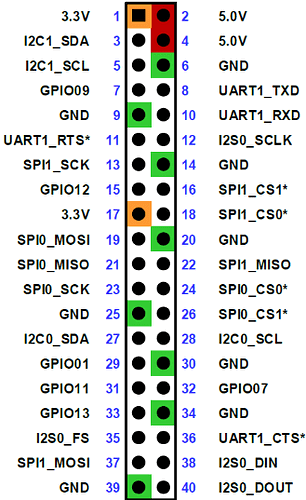
 Design with GPIO pin header for Jetson Orin Nano in Cirkit Designer
Introduction
The GPIO pin header (J41) on the Nvidia Jetson Orin Nano is a 40-pin connector that provides access to the board's general-purpose input/output (GPIO) pins. These pins enable communication with a wide range of peripherals, sensors, and external devices, making the J41 pin header a versatile interface for prototyping and embedded system development.
The J41 pin header is compatible with standard 40-pin GPIO layouts, similar to those found on Raspberry Pi boards, allowing for easy integration with existing hardware and accessories. It supports digital I/O, I2C, SPI, UART, and PWM functionalities, making it ideal for robotics, IoT, and AI-based applications.
Explore Projects Built with GPIO pin header for Jetson Orin Nano
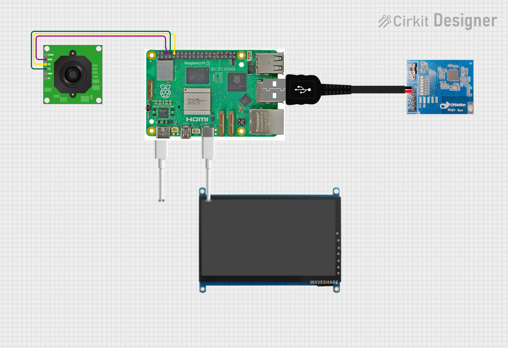 Open Project in Cirkit Designer
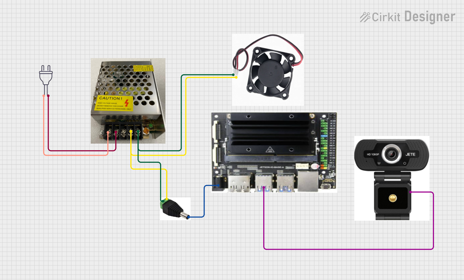 Open Project in Cirkit Designer
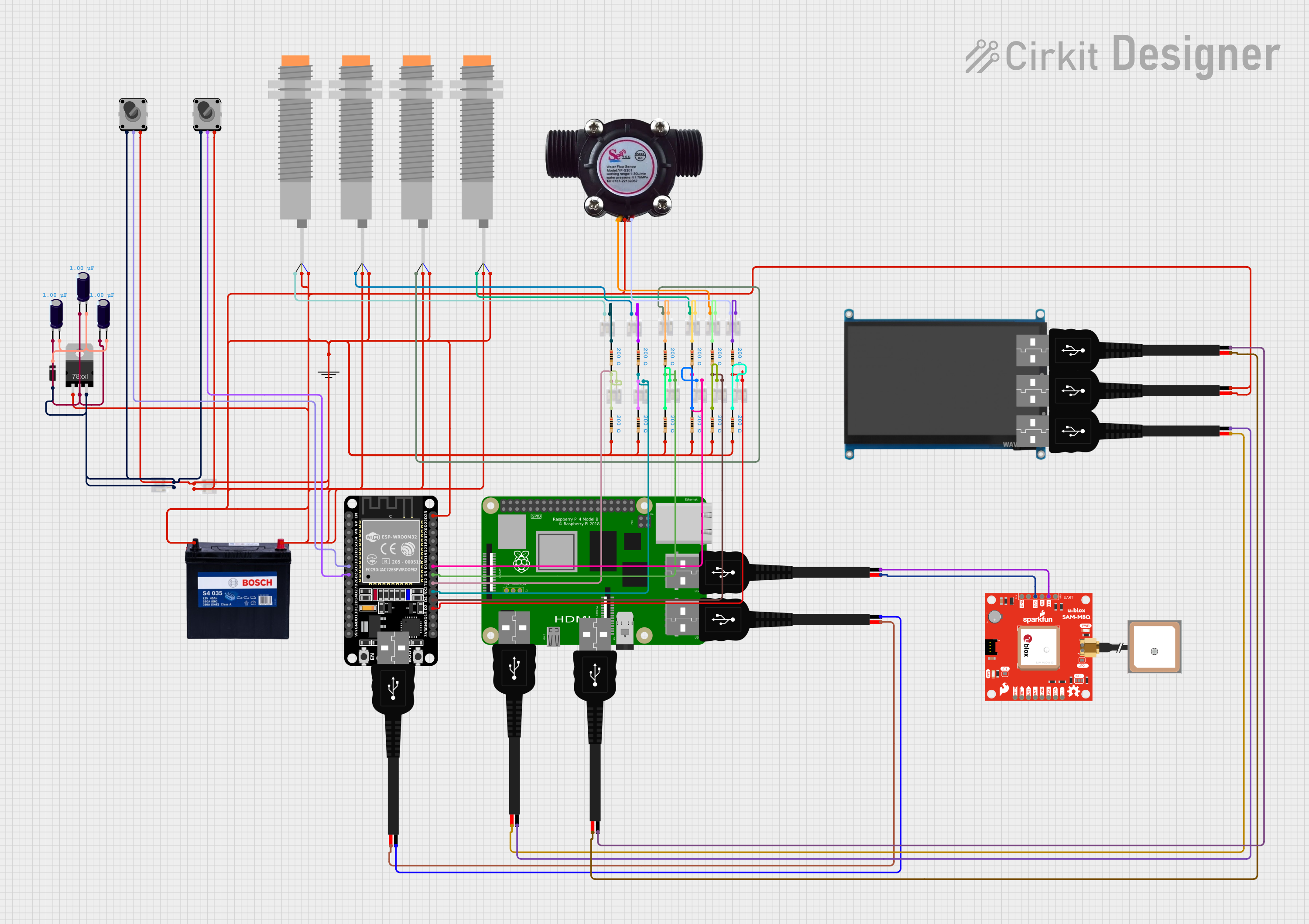 Open Project in Cirkit Designer
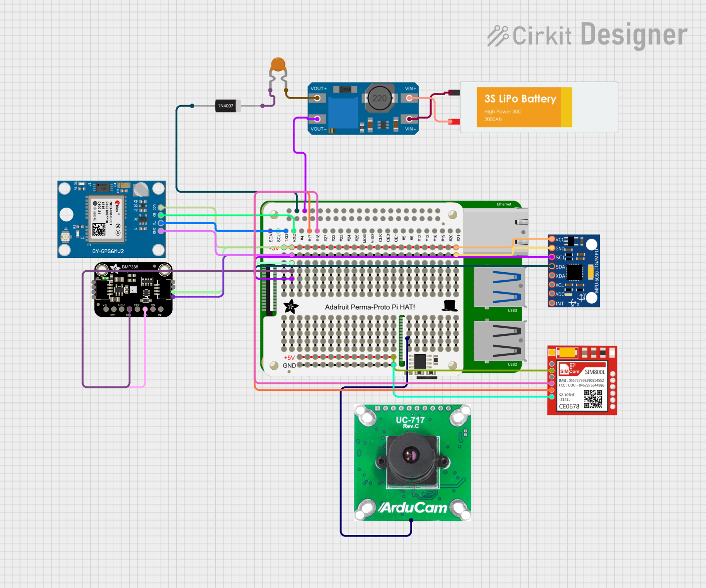 Open Project in Cirkit Designer
Explore Projects Built with GPIO pin header for Jetson Orin Nano
Open Project in Cirkit DesignerOpen Project in Cirkit DesignerOpen Project in Cirkit DesignerOpen Project in Cirkit DesignerTechnical Specifications
Key Technical Details
- Manufacturer: Nvidia
- Part ID: J41 pin header
- Number of Pins: 40 (2x20 layout)
- Voltage Levels: 3.3V logic level (5V-tolerant on some pins)
- Supported Protocols: GPIO, I2C, SPI, UART, PWM
- Maximum Current: 1.5A (shared across 5V and 3.3V power pins)
- Pin Pitch: 2.54mm (standard 0.1-inch spacing)
Pin Configuration and Descriptions
The J41 pin header follows a 40-pin layout, with pins numbered sequentially from 1 to 40. The table below provides a detailed description of each pin:
| Pin Number | Pin Name | Function/Description | Voltage Level |
|---|---|---|---|
| 1 | 3.3V Power | Power supply output | 3.3V |
| 2 | 5V Power | Power supply output | 5V |
| 3 | I2C SDA | I2C Data Line | 3.3V |
| 4 | 5V Power | Power supply output | 5V |
| 5 | I2C SCL | I2C Clock Line | 3.3V |
| 6 | GND | Ground | 0V |
| 7 | GPIO4 | General-purpose I/O | 3.3V |
| 8 | UART TX | UART Transmit | 3.3V |
| 9 | GND | Ground | 0V |
| 10 | UART RX | UART Receive | 3.3V |
| ... | ... | ... (remaining pins follow similar logic) | ... |
| 39 | GND | Ground | 0V |
| 40 | GPIO21 | General-purpose I/O | 3.3V |
Note: For the full pinout and additional details, refer to the official Nvidia Jetson Orin Nano documentation.
Usage Instructions
How to Use the Component in a Circuit
Connecting Peripherals:
- Use a 40-pin ribbon cable or directly connect jumper wires to the J41 header.
- Ensure proper alignment of pins to avoid incorrect connections.
Powering External Devices:
- Use the 3.3V or 5V power pins to supply power to external devices.
- Ensure the total current draw does not exceed 1.5A.
Programming GPIO Pins:
- Configure GPIO pins as input or output using the Jetson GPIO library.
- Use appropriate pull-up or pull-down resistors if required.
Interfacing Protocols:
- For I2C, connect SDA and SCL lines to compatible devices.
- For SPI, connect MISO, MOSI, SCLK, and CS pins as per the device's requirements.
- For UART, connect TX and RX pins to the corresponding pins on the external device.
Important Considerations and Best Practices
- Voltage Compatibility: The GPIO pins operate at 3.3V logic levels. Avoid directly connecting 5V signals to GPIO pins unless they are explicitly marked as 5V-tolerant.
- Pin Protection: Use level shifters or resistors to protect GPIO pins when interfacing with higher voltage devices.
- Static Discharge: Handle the board and peripherals with care to avoid damage from electrostatic discharge (ESD).
- Software Configuration: Install the Jetson.GPIO Python library to control GPIO pins programmatically.
Example Code for GPIO Control with Jetson.GPIO
Below is an example of how to toggle a GPIO pin using the Jetson.GPIO library:
import Jetson.GPIO as GPIO
import time
Pin Definitions
output_pin = 7 # GPIO pin number (physical pin 7 on J41 header)
Pin Setup
GPIO.setmode(GPIO.BOARD) # Use physical pin numbering GPIO.setup(output_pin, GPIO.OUT) # Set pin as an output pin
print("Toggling GPIO pin...") try: while True: GPIO.output(output_pin, GPIO.HIGH) # Set pin high time.sleep(1) # Wait for 1 second GPIO.output(output_pin, GPIO.LOW) # Set pin low time.sleep(1) # Wait for 1 second except KeyboardInterrupt: print("Exiting program...")
Cleanup
GPIO.cleanup() # Reset GPIO settings
> **Note**: Replace `output_pin` with the desired GPIO pin number. Ensure the pin is not being used by other processes.
Troubleshooting and FAQs
Common Issues Users Might Face
GPIO Pin Not Responding:
- Cause: The pin may be configured incorrectly or used by another process.
- Solution: Check the pin configuration and ensure no other process is using the pin. Use the
sudocommand if necessary to run scripts with elevated privileges.
Peripheral Not Detected:
- Cause: Incorrect wiring or protocol configuration.
- Solution: Verify the connections and ensure the correct protocol (I2C, SPI, UART) is configured in software.
Overcurrent on Power Pins:
- Cause: Excessive current draw from external devices.
- Solution: Ensure the total current draw does not exceed 1.5A. Use an external power supply if needed.
GPIO Library Not Installed:
- Cause: The Jetson.GPIO library is missing.
- Solution: Install the library using the command:
sudo pip3 install Jetson.GPIO
Solutions and Tips for Troubleshooting
- Use a multimeter to check voltage levels on the pins.
- Refer to the Jetson Orin Nano's official documentation for detailed pinout and configuration settings.
- Test GPIO functionality with a simple LED circuit before connecting complex peripherals.
By following this documentation, users can effectively utilize the J41 GPIO pin header on the Nvidia Jetson Orin Nano for a wide range of applications.