How to Use Дисплей: Examples, Pinouts, and Specs
Introduction
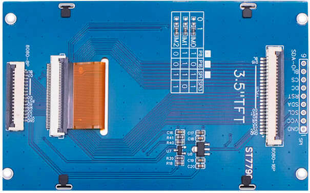
The ST7796 is a high-performance TFT-LCD controller/driver manufactured by SITRONIX. It is designed to drive TFT displays with resolutions up to 320x480 pixels, supporting 16.7M colors. This display controller is widely used in applications requiring vibrant graphical interfaces, such as handheld devices, industrial control panels, and embedded systems.
Common applications and use cases:
- Handheld devices (e.g., smart home controllers, portable gaming consoles)
- Industrial control systems
- Consumer electronics (e.g., smart appliances, dashboards)
- Educational and hobbyist projects (e.g., Arduino and Raspberry Pi displays)
Explore Projects Built with Дисплей
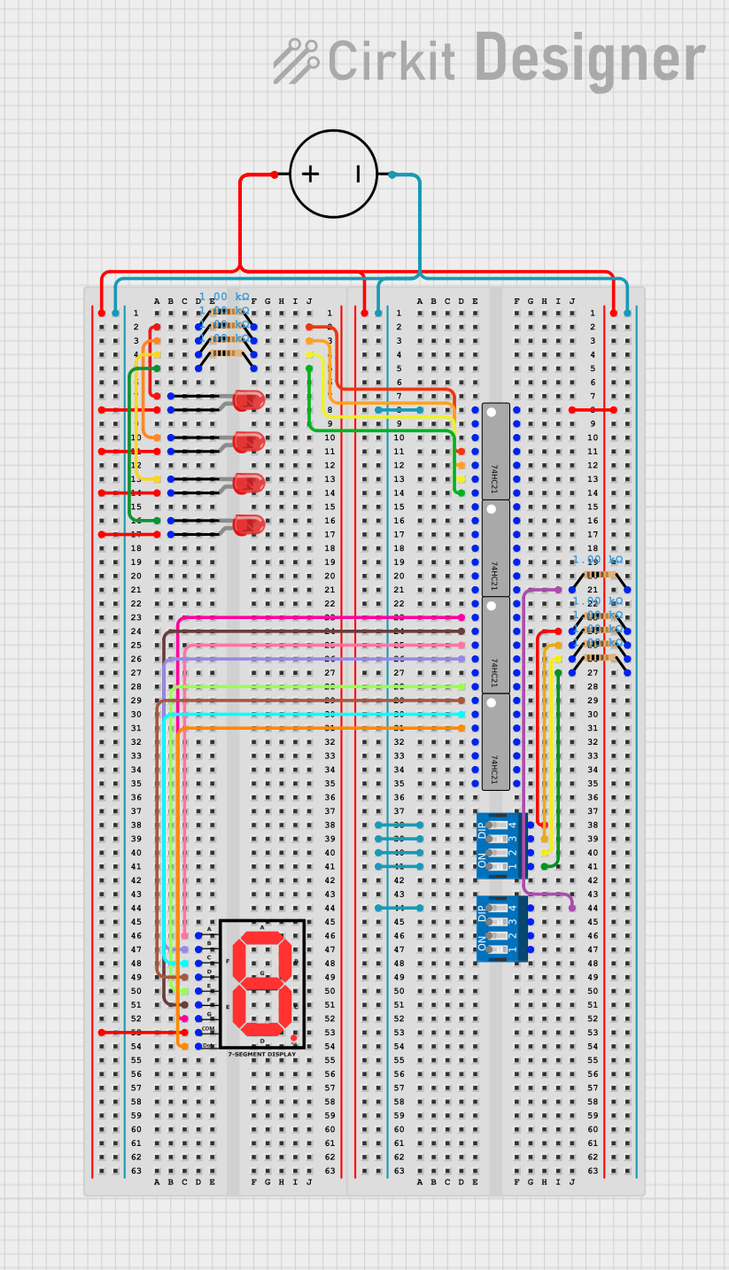

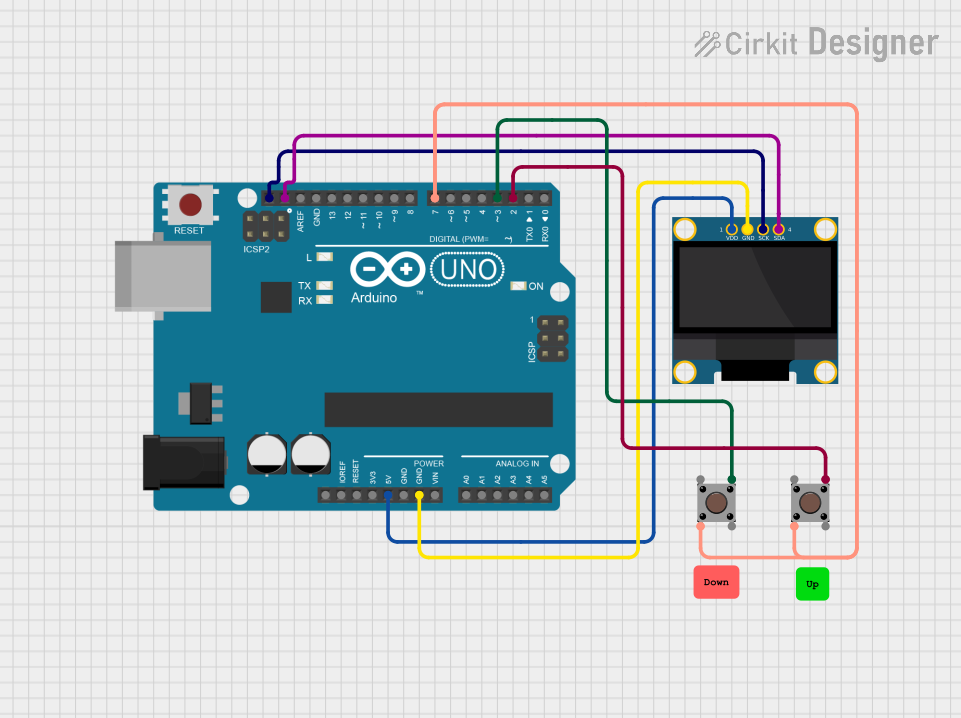
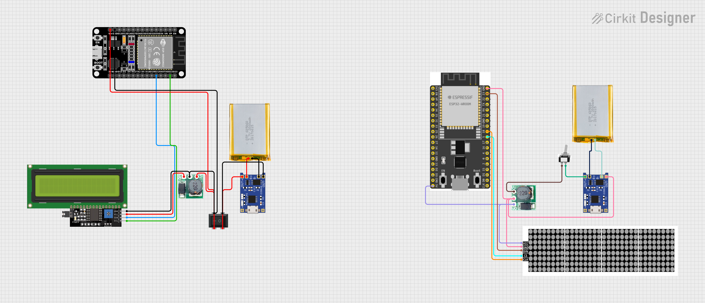
Explore Projects Built with Дисплей
Technical Specifications
The ST7796 display controller offers robust performance and versatile interfacing options. Below are the key technical details:
Key Specifications
| Parameter | Value |
|---|---|
| Resolution | Up to 320x480 pixels |
| Color Depth | 16.7M colors (24-bit RGB) |
| Interface | Parallel (8080/6800), SPI |
| Operating Voltage (VDD) | 2.5V to 3.3V |
| Logic Voltage (IOVCC) | 1.65V to 3.3V |
| Operating Temperature | -30°C to 85°C |
| Frame Rate | Up to 120 fps |
| Backlight Control | PWM or external circuit |
Pin Configuration
The ST7796 display module typically includes a 40-pin interface. Below is a table describing the key pins:
| Pin No. | Pin Name | Description |
|---|---|---|
| 1 | VDD | Power supply for the display (2.5V to 3.3V) |
| 2 | GND | Ground |
| 3 | CS | Chip Select (active low) |
| 4 | RS/DC | Register Select/Data Command (high for data) |
| 5 | WR | Write signal (active low) |
| 6 | RD | Read signal (active low) |
| 7-22 | DB0-DB15 | Data bus lines (used in parallel interface) |
| 23 | RESET | Reset signal (active low) |
| 24 | BL_PWM | Backlight PWM control |
| 25 | BL_EN | Backlight enable |
| 26-40 | NC | Not connected or reserved for future use |
Note: The exact pinout may vary depending on the specific module or breakout board used. Always refer to the datasheet or module documentation.
Usage Instructions
The ST7796 display can be interfaced with microcontrollers such as Arduino, STM32, or Raspberry Pi. Below are the steps to use the display in a circuit:
Connecting the Display
- Power Supply: Connect the VDD pin to a 3.3V power source and GND to ground.
- Control Pins: Connect the CS, RS/DC, WR, and RD pins to the corresponding GPIO pins on your microcontroller.
- Data Bus: For parallel communication, connect DB0-DB15 to the microcontroller's data pins. For SPI, connect only the necessary pins (e.g., MOSI, SCK).
- Backlight: Use the BL_PWM and BL_EN pins to control the backlight. A PWM signal can adjust brightness.
- Reset: Connect the RESET pin to a GPIO pin or pull it high with a resistor.
Arduino Example Code
Below is an example of interfacing the ST7796 display with an Arduino UNO using the SPI interface:
#include <Adafruit_GFX.h>    // Graphics library for displays
#include <Adafruit_ST7796.h> // Library for ST7796 driver

// Define SPI pins for the display
#define TFT_CS   10  // Chip Select pin
#define TFT_DC   9   // Data/Command pin
#define TFT_RST  8   // Reset pin

// Create an instance of the display
Adafruit_ST7796 tft = Adafruit_ST7796(TFT_CS, TFT_DC, TFT_RST);

void setup() {
  // Initialize the display
  tft.begin();

  // Set rotation (0-3)
  tft.setRotation(1);

  // Fill the screen with a color
  tft.fillScreen(ST77XX_BLUE);

  // Draw a rectangle
  tft.fillRect(50, 50, 100, 100, ST77XX_RED);

  // Display text
  tft.setTextColor(ST77XX_WHITE);
  tft.setTextSize(2);
  tft.setCursor(10, 10);
  tft.print("Hello, ST7796!");
}

void loop() {
  // Add any dynamic updates here
}
Important Considerations:
- Ensure the display's operating voltage matches your microcontroller's logic level (use level shifters if necessary).
- Use decoupling capacitors near the power pins to reduce noise.
- Avoid long wires for SPI or parallel connections to minimize signal degradation.
Troubleshooting and FAQs
Common Issues
Display not turning on:
- Verify the power supply voltage and connections.
- Check the RESET pin; it should be pulled high after initialization.
No image or incorrect colors:
- Ensure the data bus or SPI connections are correct.
- Verify the initialization code matches the display's configuration.
Flickering or unstable display:
- Check the backlight control circuit.
- Use shorter wires or shielded cables for SPI/parallel connections.
Arduino code not working:
- Ensure the correct library (e.g., Adafruit_ST7796) is installed.
- Double-check pin definitions in the code.
FAQs
Q: Can I use the ST7796 with a 5V microcontroller?
A: Yes, but you must use level shifters to convert the 5V logic signals to 3.3V.
Q: How do I adjust the brightness of the display?
A: Use a PWM signal on the BL_PWM pin to control the backlight brightness.
Q: What is the maximum frame rate supported?
A: The ST7796 supports frame rates up to 120 fps, depending on the resolution and interface.
Q: Can I use the ST7796 with Raspberry Pi?
A: Yes, the ST7796 can be interfaced with Raspberry Pi using SPI or parallel GPIO connections. Use appropriate libraries like fbtft or rpi-fbcp.
By following this documentation, you can effectively integrate the ST7796 display into your projects and troubleshoot common issues.