How to Use SPI Flash Breakout Board: Examples, Pinouts, and Specs
Introduction
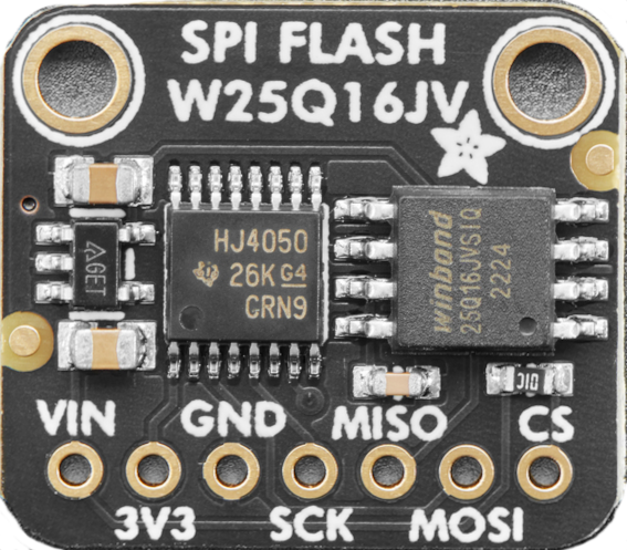
The SPI Flash Breakout Board (Manufacturer: Adafruit, Part ID: W25Q15JV) is a compact and versatile printed circuit board (PCB) designed to interface with SPI flash memory chips. It provides easy access to the chip's pins, enabling seamless programming, data transfer, and integration into various projects. This breakout board is ideal for developers and hobbyists working with SPI-based storage solutions.
Explore Projects Built with SPI Flash Breakout Board
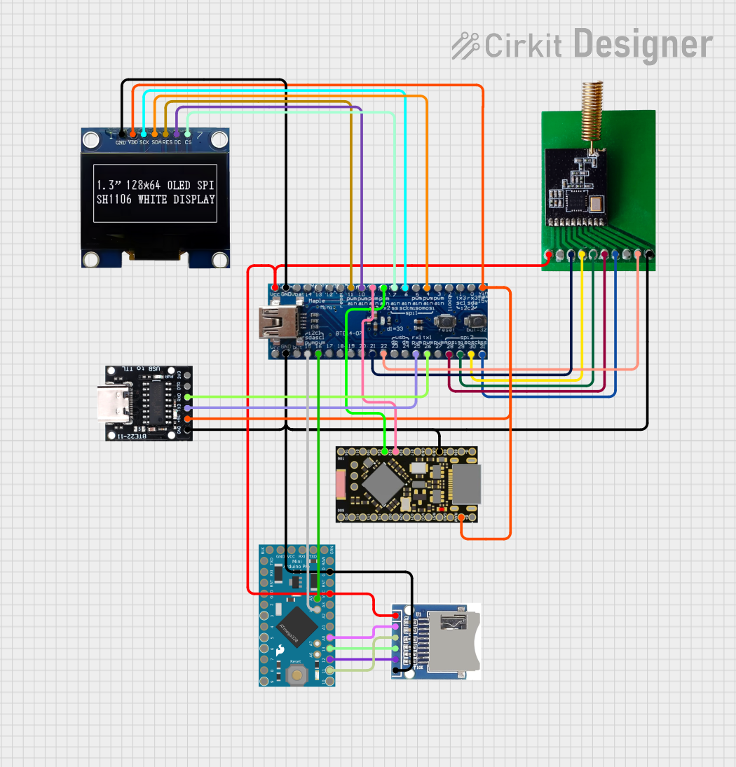
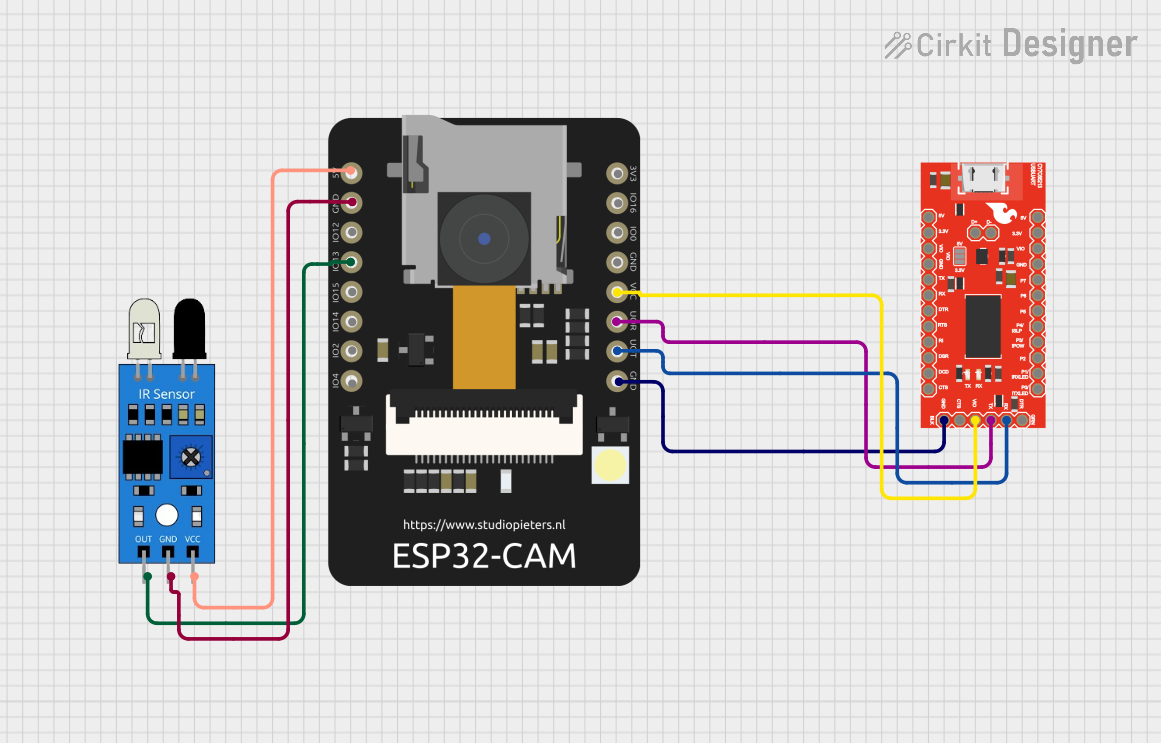
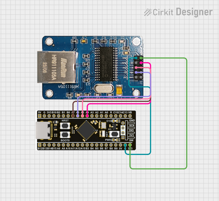

Explore Projects Built with SPI Flash Breakout Board
Common Applications and Use Cases
- Data Logging: Store sensor data or logs in non-volatile memory.
- Firmware Storage: Use as external storage for microcontroller firmware.
- Bootloaders: Store bootloader code for embedded systems.
- Prototyping: Quickly test and evaluate SPI flash memory chips.
- IoT Devices: Store configuration files or temporary data for IoT applications.
Technical Specifications
The following are the key technical details of the Adafruit SPI Flash Breakout Board (W25Q15JV):
General Specifications
- Memory Type: SPI NOR Flash
- Memory Capacity: 16 Mbit (2 MB)
- Interface: SPI (Serial Peripheral Interface)
- Operating Voltage: 3.3V (logic level)
- Power Consumption:
- Active Read: ~4 mA
- Standby: ~1 µA
- Operating Temperature: -40°C to +85°C
- Dimensions: 0.8" x 0.6" (20.3 mm x 15.2 mm)
Pin Configuration and Descriptions
The breakout board exposes the following pins for easy interfacing:
| Pin Name | Pin Type | Description |
|---|---|---|
GND |
Power | Ground connection. Connect to the ground of your circuit. |
3V3 |
Power | 3.3V power input. Supplies power to the SPI flash chip. |
CS |
Digital Input | Chip Select. Active low; used to enable communication with the flash chip. |
SCK |
Digital Input | Serial Clock. Provides the clock signal for SPI communication. |
MOSI |
Digital Input | Master Out Slave In. Transfers data from the microcontroller to the flash chip. |
MISO |
Digital Output | Master In Slave Out. Transfers data from the flash chip to the microcontroller. |
WP |
Digital Input | Write Protect. Active low; prevents write operations when asserted. |
HOLD |
Digital Input | Hold. Active low; pauses communication when asserted. |
Usage Instructions
How to Use the Component in a Circuit
- Power the Board: Connect the
3V3pin to a 3.3V power source and theGNDpin to ground. - Connect SPI Pins: Interface the
CS,SCK,MOSI, andMISOpins to the corresponding SPI pins on your microcontroller. - Optional Pins:
- Connect the
WPpin to3V3if write protection is not required. - Connect the
HOLDpin to3V3if the hold function is not needed.
- Connect the
- Initialize SPI Communication: Configure your microcontroller to communicate with the SPI flash chip using the SPI protocol.
Important Considerations and Best Practices
- Voltage Levels: Ensure that your microcontroller operates at 3.3V logic levels. If it operates at 5V, use a level shifter to avoid damaging the breakout board.
- Pull-Up Resistors: The
WPandHOLDpins have internal pull-up resistors, so they can be left unconnected if not used. - SPI Speed: The W25Q15JV supports SPI clock speeds up to 104 MHz. Ensure your microcontroller's SPI clock is within this range.
- Data Retention: The flash memory guarantees data retention for at least 20 years under normal operating conditions.
Example Code for Arduino UNO
Below is an example of how to interface the SPI Flash Breakout Board with an Arduino UNO:
#include <SPI.h>

// Define SPI pins for the breakout board
#define CS_PIN 10  // Chip Select pin connected to Arduino pin 10

void setup() {
  // Initialize Serial Monitor for debugging
  Serial.begin(9600);
  while (!Serial);

  // Initialize SPI communication
  SPI.begin();
  pinMode(CS_PIN, OUTPUT);
  digitalWrite(CS_PIN, HIGH); // Set CS pin to inactive state

  Serial.println("SPI Flash Breakout Board Initialized");
}

void loop() {
  // Example: Read the Manufacturer ID from the flash chip
  digitalWrite(CS_PIN, LOW); // Select the flash chip
  SPI.transfer(0x90);        // Send "Read Manufacturer ID" command
  SPI.transfer(0x00);        // Send dummy address byte 1
  SPI.transfer(0x00);        // Send dummy address byte 2
  SPI.transfer(0x00);        // Send dummy address byte 3
  byte manufacturerID = SPI.transfer(0x00); // Read Manufacturer ID
  digitalWrite(CS_PIN, HIGH); // Deselect the flash chip

  // Print the Manufacturer ID
  Serial.print("Manufacturer ID: 0x");
  Serial.println(manufacturerID, HEX);

  delay(1000); // Wait for 1 second before repeating
}
Troubleshooting and FAQs
Common Issues and Solutions
No Communication with the Flash Chip:
- Ensure the
CS,SCK,MOSI, andMISOpins are correctly connected. - Verify that the
CSpin is set toLOWduring communication andHIGHotherwise. - Check the SPI clock speed and ensure it is within the supported range.
- Ensure the
Data Corruption:
- Verify that the power supply is stable and within the 3.3V range.
- Avoid writing to the flash memory during power fluctuations.
Write Operations Failing:
- Ensure the
WPpin is not asserted (LOW). - Check if the flash memory is write-protected via software commands.
- Ensure the
Arduino Code Not Working:
- Confirm that the
CS_PINdefinition matches the actual pin used on the Arduino. - Ensure the SPI library is correctly included and initialized.
- Confirm that the
FAQs
Q: Can I use this breakout board with a 5V microcontroller?
A: Yes, but you must use a level shifter to convert the 5V logic levels to 3.3V to avoid damaging the board.
Q: How do I erase data on the flash chip?
A: Use the "Chip Erase" or "Sector Erase" SPI commands as specified in the W25Q15JV datasheet.
Q: What is the maximum number of write cycles supported?
A: The W25Q15JV supports up to 100,000 write/erase cycles per sector.
Q: Can I use this board for high-speed data logging?
A: Yes, the board supports SPI clock speeds up to 104 MHz, making it suitable for high-speed applications.