
How to Use TB6600 DRIVER: Examples, Pinouts, and Specs
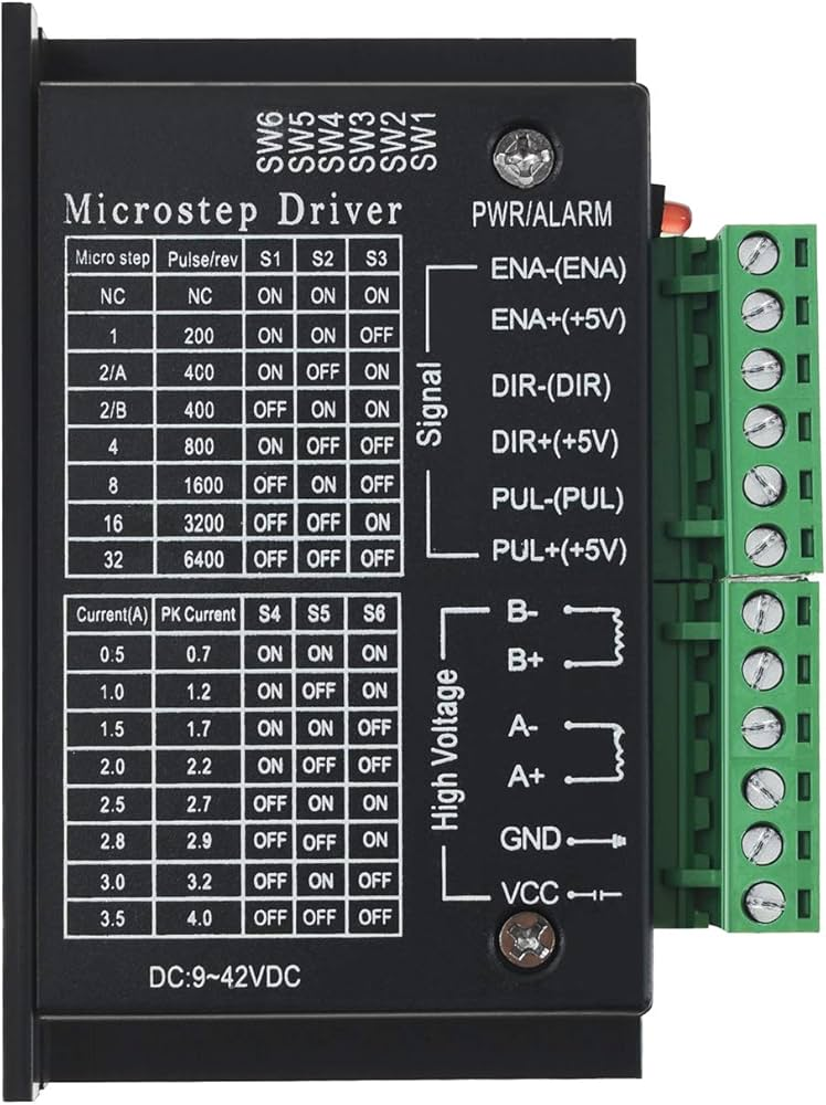
 Design with TB6600 DRIVER in Cirkit Designer
Introduction
The TB6600 is a stepper motor driver designed to provide precise control of stepper motors. It enables smooth operation and delivers high torque across a wide range of speeds. This driver is widely used in applications requiring accurate motor control, such as CNC machines, 3D printers, robotics, and automation systems. With adjustable current settings and support for microstepping, the TB6600 ensures enhanced performance and flexibility for various motor control needs.
Explore Projects Built with TB6600 DRIVER
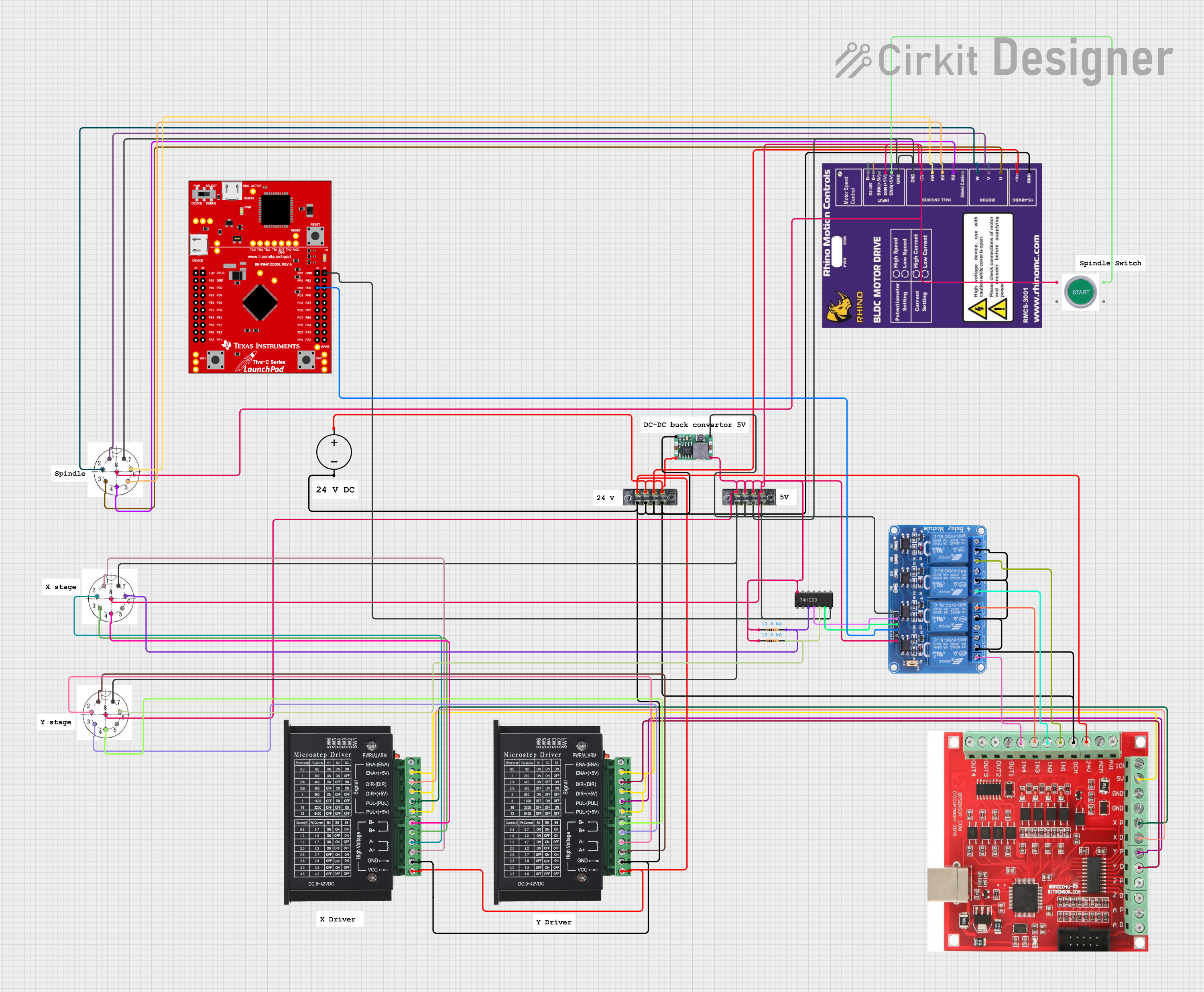 Open Project in Cirkit Designer
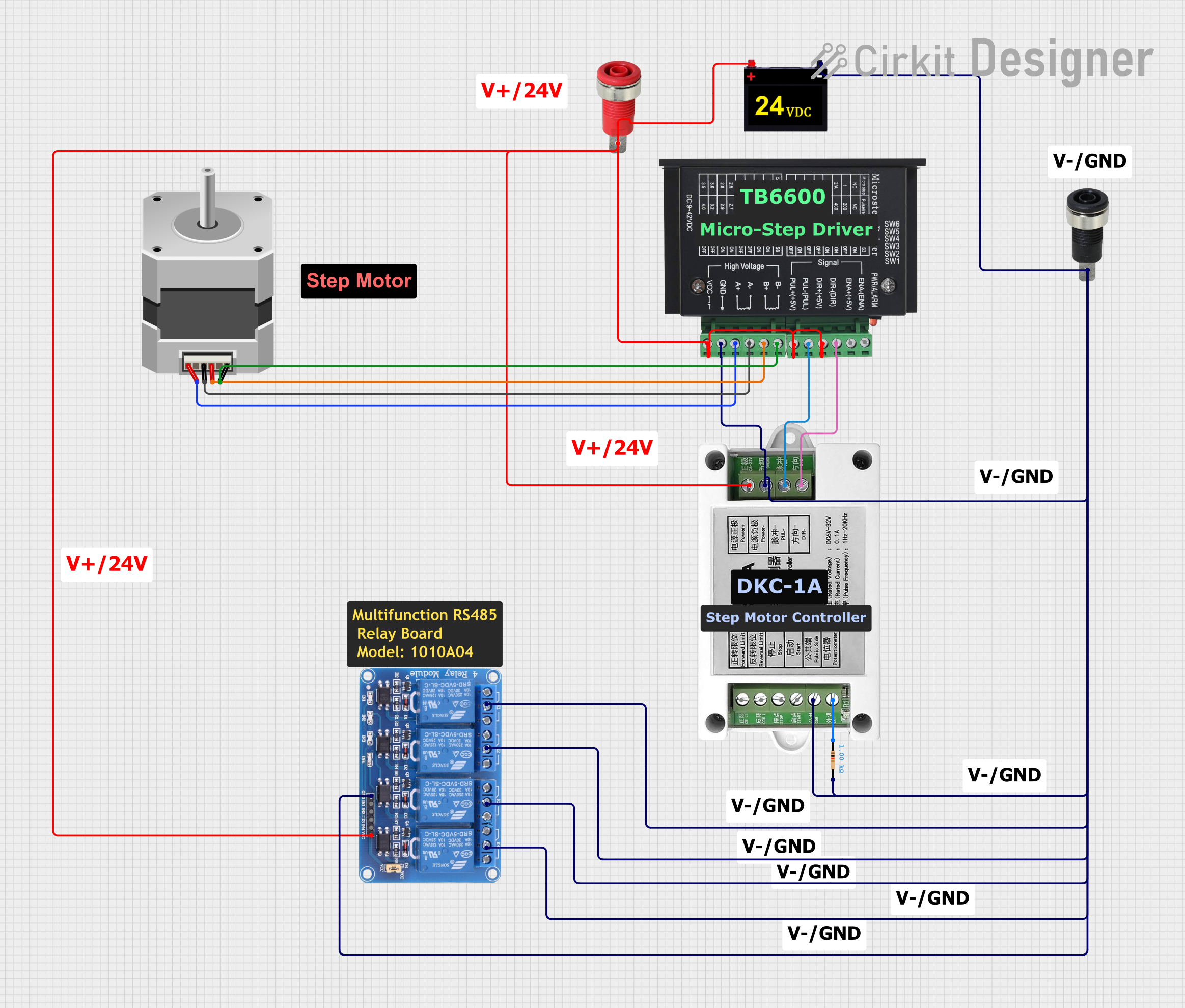 Open Project in Cirkit Designer
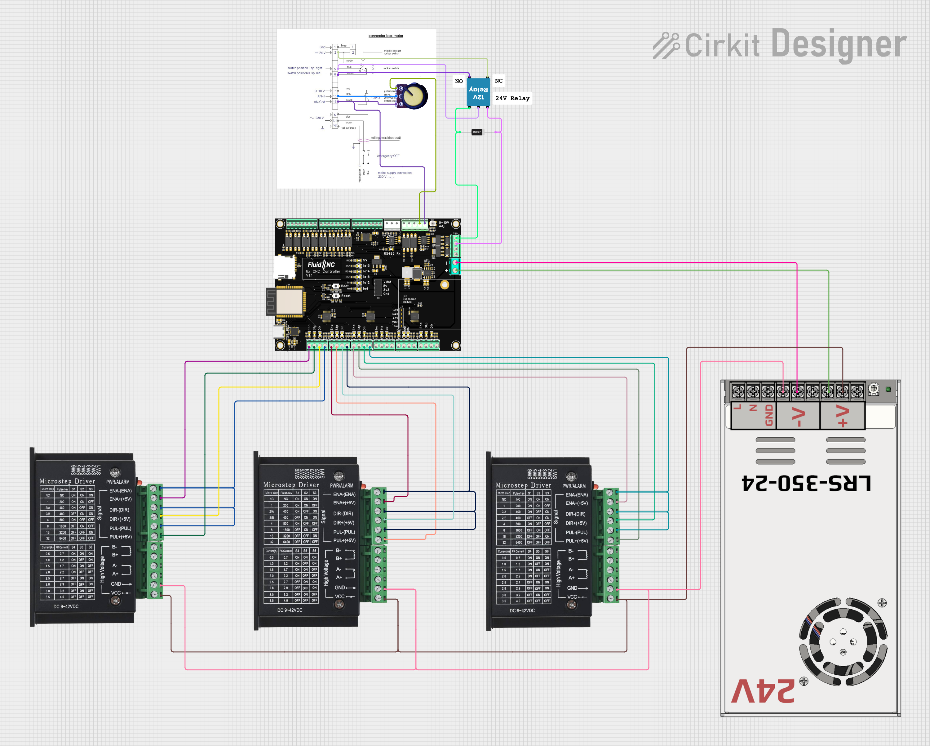 Open Project in Cirkit Designer
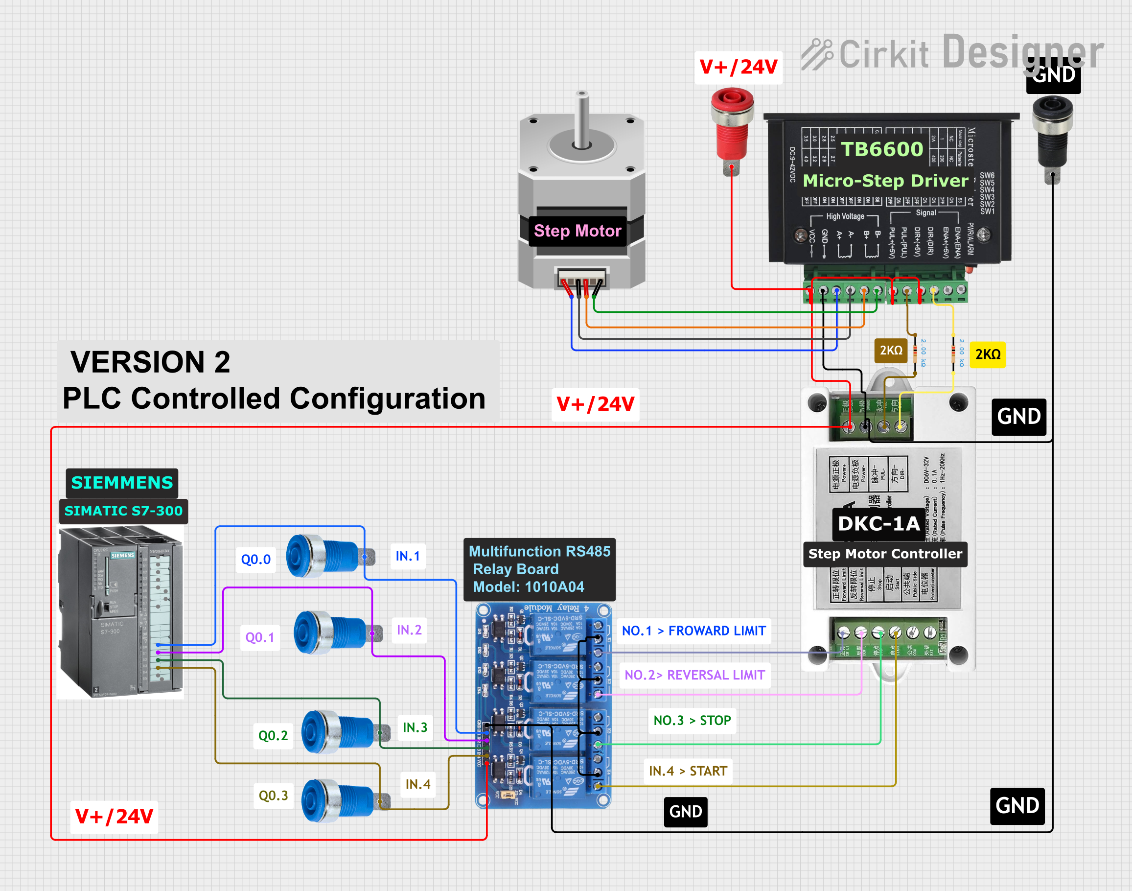 Open Project in Cirkit Designer
Explore Projects Built with TB6600 DRIVER
Open Project in Cirkit DesignerOpen Project in Cirkit DesignerOpen Project in Cirkit DesignerOpen Project in Cirkit DesignerTechnical Specifications
The TB6600 driver is equipped with robust features to handle demanding motor control tasks. Below are its key technical specifications:
Key Specifications
- Input Voltage: 9V to 42V DC
- Output Current: Adjustable, up to 4.5A (peak)
- Microstepping: 1, 2, 4, 8, 16, or 32 steps
- Control Signal Voltage: 3.3V to 5V (compatible with most microcontrollers)
- Operating Temperature: -10°C to +45°C
- Protection Features: Overcurrent, overvoltage, and thermal protection
- Dimensions: 96mm x 56mm x 33mm
Pin Configuration and Descriptions
The TB6600 driver has several input and output terminals for connecting to a microcontroller, power supply, and stepper motor. Below is the pin configuration:
| Pin Name | Type | Description |
|---|---|---|
VCC |
Power Input | Connect to a DC power supply (9V to 42V). |
GND |
Power Ground | Ground connection for the power supply. |
A+, A- |
Motor Output | Connect to one coil of the stepper motor. |
B+, B- |
Motor Output | Connect to the other coil of the stepper motor. |
PUL+, PUL- |
Control Input | Pulse signal input for controlling motor steps. |
DIR+, DIR- |
Control Input | Direction signal input to set motor rotation direction. |
ENA+, ENA- |
Control Input | Enable signal input to activate or deactivate the driver (optional). |
Usage Instructions
How to Use the TB6600 in a Circuit
- Power Supply: Connect a DC power supply (9V to 42V) to the
VCCandGNDterminals. Ensure the power supply can provide sufficient current for your stepper motor. - Stepper Motor Connection: Connect the stepper motor coils to the
A+,A-,B+, andB-terminals. Refer to your motor's datasheet to identify the correct coil pairs. - Microcontroller Interface:
- Connect the
PUL+,DIR+, andENA+pins to the microcontroller's digital output pins. - Connect the
PUL-,DIR-, andENA-pins to the microcontroller's ground.
- Connect the
- Microstepping Configuration: Use the DIP switches on the TB6600 to set the desired microstepping mode and current limit. Refer to the TB6600 datasheet for the DIP switch settings.
- Programming: Write a program on your microcontroller to send pulse and direction signals to the TB6600. The pulse signal controls the stepper motor's movement, while the direction signal determines its rotation direction.
Important Considerations and Best Practices
- Ensure the power supply voltage matches the requirements of both the TB6600 and the stepper motor.
- Avoid exceeding the maximum current rating of the driver to prevent damage.
- Use proper heat dissipation methods, such as a heatsink or fan, to prevent overheating during operation.
- Double-check all connections before powering on the circuit to avoid short circuits or incorrect wiring.
Example Code for Arduino UNO
Below is an example code to control a stepper motor using the TB6600 and an Arduino UNO:
// Define pin connections
#define PUL_PIN 3  // Pulse signal pin
#define DIR_PIN 4  // Direction signal pin
#define ENA_PIN 5  // Enable signal pin

void setup() {
  pinMode(PUL_PIN, OUTPUT); // Set pulse pin as output
  pinMode(DIR_PIN, OUTPUT); // Set direction pin as output
  pinMode(ENA_PIN, OUTPUT); // Set enable pin as output

  digitalWrite(ENA_PIN, LOW); // Enable the driver (LOW = enabled)
}

void loop() {
  digitalWrite(DIR_PIN, HIGH); // Set direction (HIGH = clockwise)

  // Generate pulses to move the motor
  for (int i = 0; i < 200; i++) { // 200 steps for one revolution (example)
    digitalWrite(PUL_PIN, HIGH); // Pulse HIGH
    delayMicroseconds(500);      // Adjust delay for speed control
    digitalWrite(PUL_PIN, LOW);  // Pulse LOW
    delayMicroseconds(500);      // Adjust delay for speed control
  }

  delay(1000); // Wait 1 second before changing direction

  digitalWrite(DIR_PIN, LOW); // Set direction (LOW = counterclockwise)

  // Generate pulses to move the motor in the opposite direction
  for (int i = 0; i < 200; i++) {
    digitalWrite(PUL_PIN, HIGH);
    delayMicroseconds(500);
    digitalWrite(PUL_PIN, LOW);
    delayMicroseconds(500);
  }

  delay(1000); // Wait 1 second before repeating
}
Troubleshooting and FAQs
Common Issues and Solutions
Motor Not Moving:
- Cause: Incorrect wiring or insufficient power supply.
- Solution: Verify all connections and ensure the power supply meets the voltage and current requirements.
Motor Vibrates but Does Not Rotate:
- Cause: Incorrect coil connections.
- Solution: Check the stepper motor datasheet and ensure the coils are connected to the correct terminals (
A+,A-,B+,B-).
Driver Overheating:
- Cause: Excessive current or poor heat dissipation.
- Solution: Adjust the current limit using the DIP switches and ensure proper cooling (e.g., heatsink or fan).
Inconsistent Motor Movement:
- Cause: Noise in control signals or incorrect microstepping settings.
- Solution: Use shielded cables for control signals and verify the DIP switch settings.
FAQs
Can the TB6600 drive a unipolar stepper motor? No, the TB6600 is designed for bipolar stepper motors only.
What is the maximum step rate supported by the TB6600? The TB6600 can handle pulse frequencies up to 200 kHz.
Do I need to use the
ENA+andENA-pins? No, these pins are optional. If not used, the driver will remain enabled by default.Can I use the TB6600 with a 3.3V microcontroller? Yes, the TB6600 supports control signal voltages from 3.3V to 5V, making it compatible with most microcontrollers.