Cirkit Designer Logo
Cirkit Designer
Your all-in-one circuit design IDE
Home / 
Component Documentation

How to Use stepper motor and driver: Examples, Pinouts, and Specs

Image of stepper motor and driver
Cirkit Designer LogoDesign with stepper motor and driver in Cirkit Designer

Introduction

A stepper motor is a type of DC motor that moves in discrete steps, allowing precise control of position, speed, and acceleration. It is commonly used in applications requiring accurate positioning, such as 3D printers, CNC machines, robotics, and camera gimbals. A stepper motor driver is an electronic device that controls the motor by sending electrical pulses to its windings, determining the direction and step size.

The combination of a stepper motor and driver enables precise motion control, making it ideal for automation and mechatronics projects.

Explore Projects Built with stepper motor and driver

Use Cirkit Designer to design, explore, and prototype these projects online. Some projects support real-time simulation. Click "Open Project" to start designing instantly!
Arduino-Controlled Stepper and DC Motor with Relay Switching
Image of Conveyor Belt & Capping Motor: A project utilizing stepper motor and driver in a practical application
This circuit controls a Nema 17 stepper motor using a DRV8825 driver module, with an Arduino UNO microcontroller dictating the step and direction. Additionally, the circuit can switch a DC motor on and off using a relay module controlled by the Arduino. The power supply provides the necessary voltage for the relay and the motor driver, which in turn powers the stepper motor, while the Arduino's firmware defines the motor's stepping behavior and the relay's switching to control the DC motor.
Cirkit Designer LogoOpen Project in Cirkit Designer
Arduino UNO-Based Stepper Motor Controller with Rotary Encoder and Key Switch
Image of Attenuator with 2 Buttons: A project utilizing stepper motor and driver in a practical application
This circuit controls a bipolar stepper motor using an Arduino UNO and a DRV8825 stepper motor driver. The Arduino reads inputs from a rotary encoder and a key switch module to manage the motor's direction and steps, powered by a 12V power supply.
Cirkit Designer LogoOpen Project in Cirkit Designer
Arduino-Controlled Stepper Motor with LCD Interface and Rotary Encoder
Image of AC Servo Motor: A project utilizing stepper motor and driver in a practical application
This circuit is designed to control a bipolar stepper motor using an Arduino Mega 2560 microcontroller and a STEPPERONLINE DM542T driver. The Arduino interfaces with a 20x4 LCD display over I2C for user feedback, a membrane matrix keypad for user input, and a rotary encoder for precise control inputs. The power supply provides the necessary voltage and current to drive the stepper motor through the DM542T driver.
Cirkit Designer LogoOpen Project in Cirkit Designer
Stepper Motor Control Circuit with Integrated Drive and Programmable Power Supply
Image of Stepper Motor & Integrated Drive: A project utilizing stepper motor and driver in a practical application
This circuit connects an integrated stepper motor drive to a bipolar stepper motor, enabling controlled movement of the motor's shaft in precise increments. The stepper motor drive receives power from a programmable DC power supply, with connections for both ground and voltage supply. There is no embedded code provided, suggesting that the stepper motor drive may be pre-programmed or manually controlled.
Cirkit Designer LogoOpen Project in Cirkit Designer

Explore Projects Built with stepper motor and driver

Use Cirkit Designer to design, explore, and prototype these projects online. Some projects support real-time simulation. Click "Open Project" to start designing instantly!
Image of Conveyor Belt & Capping Motor: A project utilizing stepper motor and driver in a practical application
Arduino-Controlled Stepper and DC Motor with Relay Switching
This circuit controls a Nema 17 stepper motor using a DRV8825 driver module, with an Arduino UNO microcontroller dictating the step and direction. Additionally, the circuit can switch a DC motor on and off using a relay module controlled by the Arduino. The power supply provides the necessary voltage for the relay and the motor driver, which in turn powers the stepper motor, while the Arduino's firmware defines the motor's stepping behavior and the relay's switching to control the DC motor.
Cirkit Designer LogoOpen Project in Cirkit Designer
Image of Attenuator with 2 Buttons: A project utilizing stepper motor and driver in a practical application
Arduino UNO-Based Stepper Motor Controller with Rotary Encoder and Key Switch
This circuit controls a bipolar stepper motor using an Arduino UNO and a DRV8825 stepper motor driver. The Arduino reads inputs from a rotary encoder and a key switch module to manage the motor's direction and steps, powered by a 12V power supply.
Cirkit Designer LogoOpen Project in Cirkit Designer
Image of AC Servo Motor: A project utilizing stepper motor and driver in a practical application
Arduino-Controlled Stepper Motor with LCD Interface and Rotary Encoder
This circuit is designed to control a bipolar stepper motor using an Arduino Mega 2560 microcontroller and a STEPPERONLINE DM542T driver. The Arduino interfaces with a 20x4 LCD display over I2C for user feedback, a membrane matrix keypad for user input, and a rotary encoder for precise control inputs. The power supply provides the necessary voltage and current to drive the stepper motor through the DM542T driver.
Cirkit Designer LogoOpen Project in Cirkit Designer
Image of Stepper Motor & Integrated Drive: A project utilizing stepper motor and driver in a practical application
Stepper Motor Control Circuit with Integrated Drive and Programmable Power Supply
This circuit connects an integrated stepper motor drive to a bipolar stepper motor, enabling controlled movement of the motor's shaft in precise increments. The stepper motor drive receives power from a programmable DC power supply, with connections for both ground and voltage supply. There is no embedded code provided, suggesting that the stepper motor drive may be pre-programmed or manually controlled.
Cirkit Designer LogoOpen Project in Cirkit Designer

Technical Specifications

Stepper Motor Specifications

Parameter Value
Step Angle 1.8° (200 steps per revolution)
Voltage Rating 12V
Current Rating 1.5A per phase
Holding Torque 4.2 kg-cm
Number of Phases 2
Shaft Diameter 5mm
Operating Temperature -20°C to 50°C

Stepper Motor Driver Specifications (e.g., A4988 Driver)

Parameter Value
Input Voltage 8V to 35V
Output Current Up to 2A per coil (with cooling)
Microstepping Modes Full, 1/2, 1/4, 1/8, 1/16
Logic Voltage 3.3V or 5V
Step Pulse Frequency Up to 500 kHz
Overcurrent Protection Yes
Thermal Shutdown Yes

Pin Configuration for A4988 Driver

Pin Name Description
VMOT Motor power supply (8V to 35V)
GND Ground for motor power supply
VDD Logic power supply (3.3V or 5V)
STEP Step pulse input (controls motor steps)
DIR Direction input (controls motor rotation direction)
ENABLE Enable/disable motor driver (active low)
MS1, MS2, MS3 Microstepping mode selection pins
1A, 1B Outputs for motor coil 1
2A, 2B Outputs for motor coil 2

Usage Instructions

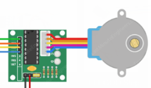
Connecting the Stepper Motor and Driver

  1. Power Supply: Connect the motor power supply (VMOT) and ground (GND) to the driver. Ensure the voltage matches the motor's rating.
  2. Logic Power: Connect the VDD pin to a 3.3V or 5V logic supply, depending on your microcontroller.
  3. Motor Connections: Connect the stepper motor's coils to the driver outputs (1A, 1B, 2A, 2B). Refer to the motor's datasheet to identify the coil pairs.
  4. Control Pins: Connect the STEP and DIR pins to your microcontroller's digital output pins. Optionally, connect ENABLE to control motor activation.
  5. Microstepping: Set the MS1, MS2, and MS3 pins to configure the desired microstepping mode.

Example Arduino UNO Code

// Define control pins for the stepper motor driver
#define STEP_PIN 3  // Pin connected to STEP on the driver
#define DIR_PIN 4   // Pin connected to DIR on the driver

void setup() {
  pinMode(STEP_PIN, OUTPUT); // Set STEP pin as output
  pinMode(DIR_PIN, OUTPUT);  // Set DIR pin as output

  digitalWrite(DIR_PIN, HIGH); // Set initial direction (HIGH = clockwise)
}

void loop() {
  // Rotate the motor one step at a time
  digitalWrite(STEP_PIN, HIGH); // Generate a step pulse
  delayMicroseconds(1000);      // Wait for 1ms (adjust for speed control)
  digitalWrite(STEP_PIN, LOW);  // End the step pulse
  delayMicroseconds(1000);      // Wait for 1ms before the next step
}

Best Practices

  • Use a heat sink or cooling fan for the driver if operating near its maximum current rating.
  • Avoid disconnecting the motor while the driver is powered, as this can damage the driver.
  • Use decoupling capacitors near the VMOT and VDD pins to reduce electrical noise.
  • Adjust the driver's current limit to match the motor's rated current to prevent overheating.

Troubleshooting and FAQs

Common Issues

  1. Motor Not Moving:

    • Check all connections, especially the motor coils and power supply.
    • Verify that the STEP and DIR pins are receiving signals from the microcontroller.
    • Ensure the driver is enabled (ENABLE pin is LOW).
  2. Motor Vibrates but Doesn't Rotate:

    • Verify the coil connections. Incorrect wiring can cause the motor to vibrate without stepping.
    • Check the microstepping configuration (MS1, MS2, MS3 pins).
  3. Driver Overheating:

    • Ensure the current limit is set correctly using the driver's potentiometer.
    • Add a heat sink or cooling fan to the driver.
  4. Motor Skipping Steps:

    • Increase the step pulse duration (delayMicroseconds in the code).
    • Ensure the power supply can provide sufficient current for the motor.

FAQs

Q: Can I use a 5V power supply for the motor?
A: Most stepper motors require higher voltages (e.g., 12V or 24V) for optimal performance. Check your motor's datasheet for the recommended voltage.

Q: How do I set the current limit on the driver?
A: Use a small screwdriver to adjust the potentiometer on the driver. Refer to the driver's datasheet for the formula to calculate the current limit.

Q: What is microstepping, and why is it useful?
A: Microstepping divides each full step into smaller steps, improving resolution and reducing vibration. It is useful for applications requiring smooth and precise motion.

Q: Can I control multiple stepper motors with one Arduino?
A: Yes, you can control multiple motors by connecting additional drivers to different digital pins on the Arduino. Ensure the Arduino has enough I/O pins and processing power for your application.