Cirkit Designer Logo
Cirkit Designer
Your all-in-one circuit design IDE
Home / 
Component Documentation

How to Use relay 8 pin: Examples, Pinouts, and Specs

Image of relay 8 pin
Cirkit Designer LogoDesign with relay 8 pin in Cirkit Designer

Introduction

A relay is an electrically operated switch that allows you to control a high-power electrical circuit with a low-power signal. The 8-pin relay module is a common electronic component used in automation systems, control circuits, and applications where switching between high current circuits with a low current signal is required.

Explore Projects Built with relay 8 pin

Use Cirkit Designer to design, explore, and prototype these projects online. Some projects support real-time simulation. Click "Open Project" to start designing instantly!
ESP32-Powered Wi-Fi Controlled 8-Channel Relay Module
Image of Olimex ESP32-POE2 8Ch Switch and Sensors: A project utilizing relay 8 pin in a practical application
This circuit features an ESP32 microcontroller connected to an 8-channel relay module. The ESP32 controls the relay channels via its GPIO pins, allowing it to switch multiple external devices on and off. The ESP32 also provides power to the relay module.
Cirkit Designer LogoOpen Project in Cirkit Designer
ESP32-Powered 8-Channel Relay Controller with Wi-Fi Connectivity
Image of Olimex ESP32-POE2 4Ch X 2 Switches: A project utilizing relay 8 pin in a practical application
This circuit features an ESP32 microcontroller connected to an 8-channel relay module. The ESP32 controls the relay channels via its GPIO pins, allowing for the switching of external devices or loads through the relays.
Cirkit Designer LogoOpen Project in Cirkit Designer
Wi-Fi Controlled Smart Relay Switch with ESP8266 and MCP23017
Image of Bed Room: A project utilizing relay 8 pin in a practical application
This circuit is designed to control an 8-channel relay module via an ESP8266 microcontroller, which interfaces with an MCP23017 I/O expander over I2C. The ESP8266 connects to a WiFi network and subscribes to MQTT topics to receive commands for toggling the relays. Additionally, there are toggle switches connected to the MCP23017 that allow manual control of the relays, with the system's state being reported back via MQTT.
Cirkit Designer LogoOpen Project in Cirkit Designer
ESP32-Controlled 4-Channel Relay Module
Image of wifi esp32: A project utilizing relay 8 pin in a practical application
This circuit connects an ESP32 microcontroller to a 4-channel 5V relay module. The ESP32's digital pins (D19, D21, D22, D23) are used to control the relay channels (IN1, IN2, IN3, IN4) respectively. The circuit is designed to allow the ESP32 to switch external devices on and off via the relay module.
Cirkit Designer LogoOpen Project in Cirkit Designer

Explore Projects Built with relay 8 pin

Use Cirkit Designer to design, explore, and prototype these projects online. Some projects support real-time simulation. Click "Open Project" to start designing instantly!
Image of Olimex ESP32-POE2 8Ch Switch and Sensors: A project utilizing relay 8 pin in a practical application
ESP32-Powered Wi-Fi Controlled 8-Channel Relay Module
This circuit features an ESP32 microcontroller connected to an 8-channel relay module. The ESP32 controls the relay channels via its GPIO pins, allowing it to switch multiple external devices on and off. The ESP32 also provides power to the relay module.
Cirkit Designer LogoOpen Project in Cirkit Designer
Image of Olimex ESP32-POE2 4Ch X 2 Switches: A project utilizing relay 8 pin in a practical application
ESP32-Powered 8-Channel Relay Controller with Wi-Fi Connectivity
This circuit features an ESP32 microcontroller connected to an 8-channel relay module. The ESP32 controls the relay channels via its GPIO pins, allowing for the switching of external devices or loads through the relays.
Cirkit Designer LogoOpen Project in Cirkit Designer
Image of Bed Room: A project utilizing relay 8 pin in a practical application
Wi-Fi Controlled Smart Relay Switch with ESP8266 and MCP23017
This circuit is designed to control an 8-channel relay module via an ESP8266 microcontroller, which interfaces with an MCP23017 I/O expander over I2C. The ESP8266 connects to a WiFi network and subscribes to MQTT topics to receive commands for toggling the relays. Additionally, there are toggle switches connected to the MCP23017 that allow manual control of the relays, with the system's state being reported back via MQTT.
Cirkit Designer LogoOpen Project in Cirkit Designer
Image of wifi esp32: A project utilizing relay 8 pin in a practical application
ESP32-Controlled 4-Channel Relay Module
This circuit connects an ESP32 microcontroller to a 4-channel 5V relay module. The ESP32's digital pins (D19, D21, D22, D23) are used to control the relay channels (IN1, IN2, IN3, IN4) respectively. The circuit is designed to allow the ESP32 to switch external devices on and off via the relay module.
Cirkit Designer LogoOpen Project in Cirkit Designer

Common Applications and Use Cases

  • Home automation systems
  • Industrial controls
  • Automotive electronics
  • Power supply control

Technical Specifications

Key Technical Details

  • Coil Voltage: Typically 5V, 12V, or 24V
  • Contact Current Rating: Up to 10A at 250VAC or 30VDC
  • Switching Voltage: Maximum 250VAC, 30VDC
  • Operational Temperature: -40°C to 85°C

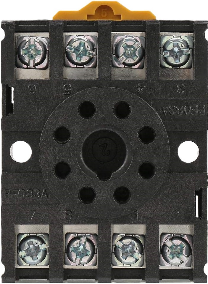
Pin Configuration and Descriptions

Pin Number Description
1 Coil End 1
2 Coil End 2
3 Common (COM)
4 Normally Closed (NC)
5 Normally Open (NO)
6 Not Connected (NC)*
7 Not Connected (NC)*
8 Not Connected (NC)*

* Pins 6, 7, and 8 are not connected in a standard 8-pin relay but are reserved for special types of relays or for manufacturer-specific functionalities.

Usage Instructions

How to Use the Component in a Circuit

  1. Powering the Coil:

    • Apply the appropriate voltage to pins 1 and 2 to energize the coil.
    • Ensure the control signal can supply sufficient current to activate the relay.
  2. Connecting the Load:

    • Connect the common terminal (pin 3) to the power source.
    • Connect the normally open terminal (pin 5) to the load if you want the load to be powered when the relay is activated.
    • Use the normally closed terminal (pin 4) if you want the load to be powered when the relay is not activated.

Important Considerations and Best Practices

  • Voltage Matching: Ensure the coil voltage matches the control signal voltage to prevent damage.
  • Current Rating: Do not exceed the current rating of the contacts to avoid overheating and potential failure.
  • Flyback Diode: Always use a flyback diode across the relay coil to prevent voltage spikes when the coil is de-energized.
  • Mounting: Secure the relay to a stable part of the circuit to prevent movement and potential disconnections.

Troubleshooting and FAQs

Common Issues Users Might Face

  • Relay Does Not Activate:

    • Check if the control signal voltage is correct and if the coil is receiving power.
    • Verify that the control signal can supply enough current to the coil.
  • Intermittent Operation:

    • Ensure all connections are secure.
    • Check for any signs of damage or wear on the relay.
  • Overheating:

    • Confirm that the current through the contacts does not exceed the rated value.
    • Check for proper ventilation around the relay.

Solutions and Tips for Troubleshooting

  • Relay Does Not Activate:

    • Measure the voltage across the relay coil with a multimeter.
    • Replace the relay if the coil is defective.
  • Intermittent Operation:

    • Resolder or replace any loose connections.
    • Replace the relay if the problem persists.
  • Overheating:

    • Reduce the load on the relay if it exceeds the rated current.
    • Consider using a relay with a higher current rating if necessary.

FAQs

Q: Can I use a 5V relay with a 12V signal? A: No, using a higher voltage than the relay is rated for can damage the coil.

Q: How do I know if my relay is working? A: You can listen for a clicking sound when the relay activates or use a multimeter to check for continuity across the contacts when activated.

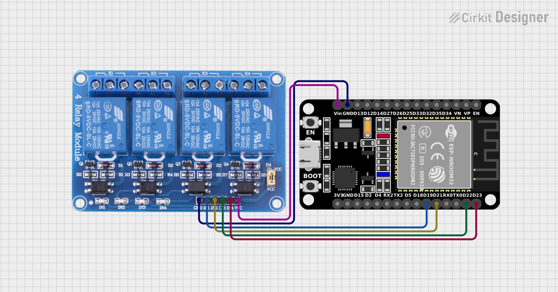
Q: Can I control this relay with an Arduino? A: Yes, you can control the relay using an Arduino digital output pin to energize the coil.

Example Arduino Code

// Define relay control pin
const int relayPin = 2;

void setup() {
  // Set the relay control pin as an output
  pinMode(relayPin, OUTPUT);
}

void loop() {
  // Turn on the relay
  digitalWrite(relayPin, HIGH);
  delay(1000); // Wait for 1 second

  // Turn off the relay
  digitalWrite(relayPin, LOW);
  delay(1000); // Wait for 1 second
}

Note: Ensure you have a suitable driver circuit or relay module with a built-in driver when connecting to an Arduino to protect the microcontroller from current spikes.