How to Use freenove-esp32-wroom: Examples, Pinouts, and Specs
Introduction
The Freenove ESP32 WROOM is a versatile microcontroller board designed for a wide range of applications, particularly in the Internet of Things (IoT) domain. Manufactured by Freenove, this board is based on the ESP32-WROOM-32 module, which features a dual-core processor, integrated Wi-Fi, and Bluetooth capabilities. Its robust design and compatibility with various sensors and modules make it an excellent choice for both beginners and experienced developers.
Explore Projects Built with freenove-esp32-wroom


Explore Projects Built with freenove-esp32-wroom
Common Applications and Use Cases
- IoT Projects: Smart home devices, environmental monitoring, and connected appliances.
- Wireless Communication: Wi-Fi and Bluetooth-based data transmission.
- Robotics: Control systems for robots and drones.
- Prototyping: Rapid development of embedded systems.
- Educational Projects: Learning microcontroller programming and hardware interfacing.
Technical Specifications
The Freenove ESP32 WROOM board is packed with features that make it suitable for a variety of applications. Below are its key technical details:
Key Technical Details
- Microcontroller: ESP32-WROOM-32 module
- Processor: Dual-core Xtensa® 32-bit LX6 CPU
- Clock Speed: Up to 240 MHz
- Flash Memory: 4 MB
- SRAM: 520 KB
- Connectivity: Wi-Fi (802.11 b/g/n), Bluetooth 4.2 (Classic and BLE)
- Operating Voltage: 3.3V
- Input Voltage: 5V (via USB) or 7-12V (via VIN pin)
- GPIO Pins: 36 (including ADC, DAC, PWM, I2C, SPI, UART)
- Analog Input Pins: 18 (12-bit ADC)
- Digital Output Pins: 36
- PWM Channels: 16
- DAC Channels: 2 (8-bit resolution)
- Operating Temperature: -40°C to 85°C
- Dimensions: 54 mm x 25 mm
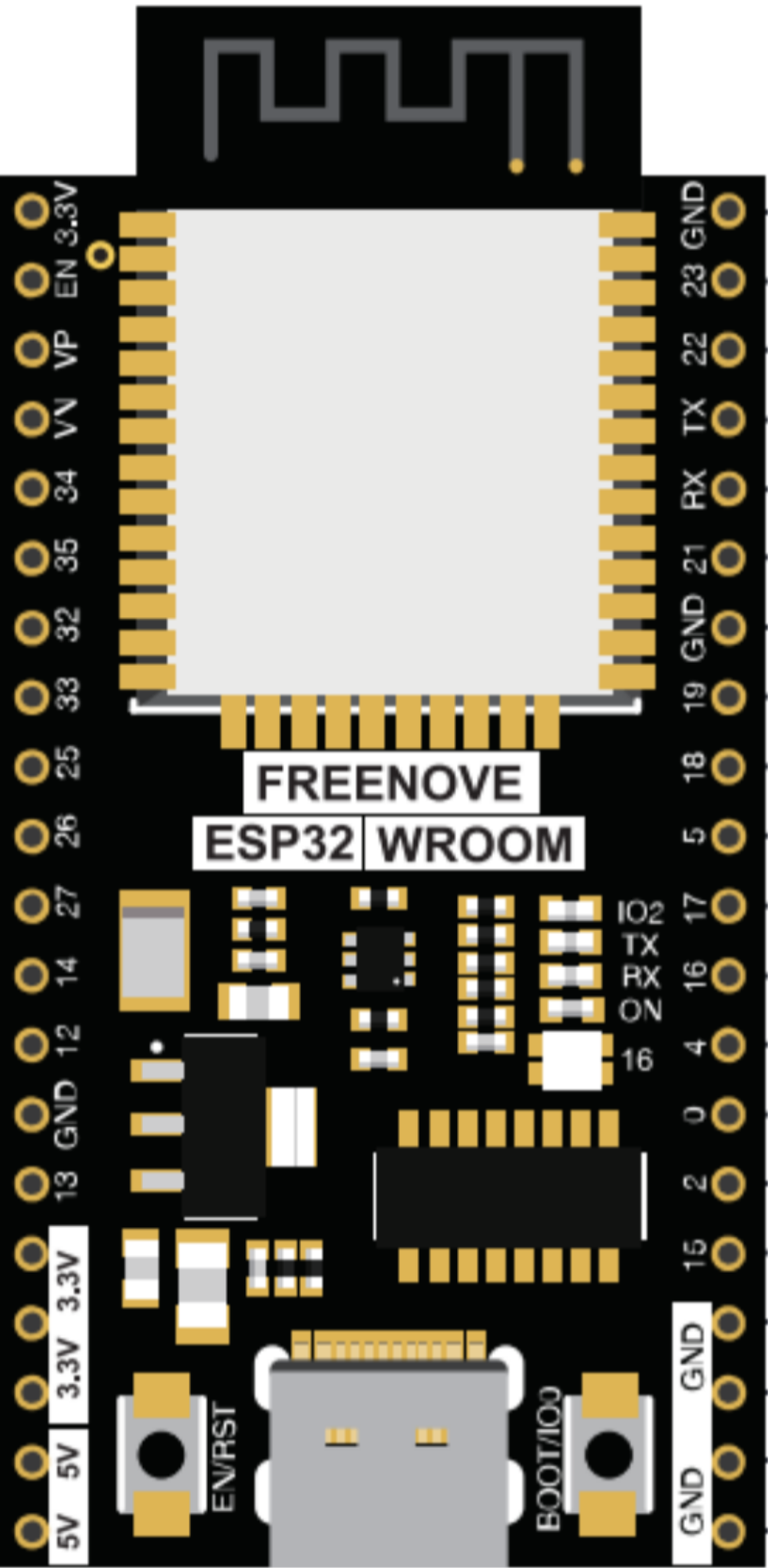
Pin Configuration and Descriptions
The Freenove ESP32 WROOM board has a total of 36 GPIO pins, each with multiple functionalities. Below is a summary of the pin configuration:
| Pin | Function | Description |
|---|---|---|
| VIN | Power Input | Accepts 7-12V input for powering the board. |
| 3V3 | Power Output | Provides 3.3V output for external components. |
| GND | Ground | Common ground for the circuit. |
| EN | Enable | Enables or disables the board. Active high. |
| GPIO0 | Boot Mode / GPIO | Used for boot mode selection or as a general-purpose pin. |
| GPIO2 | ADC / DAC / PWM | Can be used as an analog input, DAC output, or PWM output. |
| GPIO4 | ADC / PWM | Analog input or PWM output. |
| GPIO5 | ADC / PWM | Analog input or PWM output. |
| GPIO12 | ADC / PWM | Analog input or PWM output. |
| GPIO13 | ADC / PWM | Analog input or PWM output. |
| GPIO14 | ADC / PWM | Analog input or PWM output. |
| GPIO15 | ADC / PWM | Analog input or PWM output. |
| GPIO16 | UART / GPIO | Can be used for UART communication or as a general-purpose pin. |
| GPIO17 | UART / GPIO | Can be used for UART communication or as a general-purpose pin. |
| GPIO18 | SPI / GPIO | SPI clock pin or general-purpose pin. |
| GPIO19 | SPI / GPIO | SPI data pin or general-purpose pin. |
| GPIO21 | I2C SDA / GPIO | I2C data line or general-purpose pin. |
| GPIO22 | I2C SCL / GPIO | I2C clock line or general-purpose pin. |
| GPIO23 | SPI / GPIO | SPI data pin or general-purpose pin. |
| GPIO25 | DAC / PWM | DAC output or PWM output. |
| GPIO26 | DAC / PWM | DAC output or PWM output. |
| GPIO27 | ADC / PWM | Analog input or PWM output. |
| GPIO32 | ADC / Touch Sensor | Analog input or capacitive touch sensor input. |
| GPIO33 | ADC / Touch Sensor | Analog input or capacitive touch sensor input. |
| GPIO34 | ADC | Analog input only. |
| GPIO35 | ADC | Analog input only. |
| GPIO36 | ADC | Analog input only. |
Usage Instructions
The Freenove ESP32 WROOM board is easy to use and can be programmed using the Arduino IDE or other development environments like PlatformIO. Below are the steps to get started:
How to Use the Component in a Circuit
- Power the Board: Connect the board to your computer via a USB cable or use an external power source (7-12V via VIN pin).
- Install Drivers: Ensure that the necessary USB-to-serial drivers (e.g., CP2102) are installed on your computer.
- Set Up the Arduino IDE:
- Install the ESP32 board package in the Arduino IDE by adding the following URL to the Board Manager:
https://dl.espressif.com/dl/package_esp32_index.json - Select "ESP32 Dev Module" as the board type.
- Install the ESP32 board package in the Arduino IDE by adding the following URL to the Board Manager:
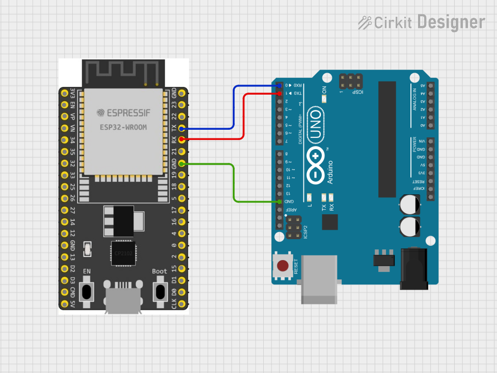
- Connect Components: Use jumper wires to connect sensors, actuators, or other modules to the GPIO pins.
- Upload Code: Write and upload your code to the board using the Arduino IDE.
Important Considerations and Best Practices
- Voltage Levels: Ensure that all connected components operate at 3.3V logic levels to avoid damaging the board.
- Pin Multiplexing: Many GPIO pins have multiple functions. Check the datasheet to avoid conflicts.
- Power Supply: Use a stable power source to prevent unexpected resets or malfunctions.
- Boot Mode: If the board does not boot, ensure that GPIO0 is not pulled low during startup.
Example Code for Arduino UNO
Here is an example of how to blink an LED connected to GPIO2:
// Define the pin for the LED
const int ledPin = 2;

void setup() {
  // Set the LED pin as an output
  pinMode(ledPin, OUTPUT);
}

void loop() {
  // Turn the LED on
  digitalWrite(ledPin, HIGH);
  delay(1000); // Wait for 1 second

  // Turn the LED off
  digitalWrite(ledPin, LOW);
  delay(1000); // Wait for 1 second
}
Troubleshooting and FAQs
Common Issues Users Might Face
- Board Not Detected by Computer:
- Ensure the USB cable is functional and supports data transfer.
- Install the correct USB-to-serial driver (e.g., CP2102).
- Code Upload Fails:
- Check that the correct board and COM port are selected in the Arduino IDE.
- Press and hold the "BOOT" button on the board while uploading the code.
- Wi-Fi Connection Issues:
- Verify the SSID and password in your code.
- Ensure the router is within range and supports 2.4 GHz Wi-Fi.
Solutions and Tips for Troubleshooting
- Reset the Board: Press the "EN" button to reset the board if it becomes unresponsive.
- Check Power Supply: Use a stable and sufficient power source to avoid brownouts.
- Debugging: Use the Serial Monitor in the Arduino IDE to print debug messages and identify issues.
By following this documentation, you can effectively utilize the Freenove ESP32 WROOM board for your projects. Happy tinkering!