
How to Use RGB LED MODULE HW-479: Examples, Pinouts, and Specs
 Design with RGB LED MODULE HW-479 in Cirkit Designer
Introduction
The RGB LED MODULE HW-479, manufactured by MAKERS ELECTRONICS, is a versatile LED module that combines red, green, and blue LEDs into a single package. This module allows users to create a wide spectrum of colors by adjusting the intensity of each LED. It is ideal for applications such as decorative lighting, displays, and projects requiring dynamic color mixing. The HW-479 is compact, easy to use, and compatible with microcontrollers like Arduino, making it a popular choice for hobbyists and professionals alike.
Explore Projects Built with RGB LED MODULE HW-479
 Open Project in Cirkit Designer
 Open Project in Cirkit Designer
 Open Project in Cirkit Designer
 Open Project in Cirkit Designer
Explore Projects Built with RGB LED MODULE HW-479
Open Project in Cirkit DesignerOpen Project in Cirkit DesignerOpen Project in Cirkit DesignerOpen Project in Cirkit DesignerTechnical Specifications
Below are the key technical details of the RGB LED MODULE HW-479:
- Manufacturer: MAKERS ELECTRONICS
- Part ID: HW-479
- Operating Voltage: 3.3V to 5V
- Current Consumption: ~20mA per channel (R, G, B)
- LED Type: Common cathode RGB LED
- Dimensions: 25mm x 15mm x 10mm
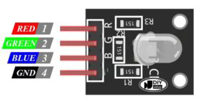
- Interface: 4-pin header (VCC, R, G, B)
- Color Control: PWM (Pulse Width Modulation)
Pin Configuration and Descriptions
The RGB LED MODULE HW-479 has a 4-pin header for easy interfacing. The pin configuration is as follows:
| Pin | Name | Description |
|---|---|---|
| 1 | VCC | Power supply input (3.3V to 5V) |
| 2 | R | Red LED control pin (PWM input) |
| 3 | G | Green LED control pin (PWM input) |
| 4 | B | Blue LED control pin (PWM input) |
Usage Instructions
How to Use the RGB LED MODULE HW-479 in a Circuit
- Power Supply: Connect the VCC pin to a 3.3V or 5V power source, depending on your system's voltage level.
- Ground Connection: Ensure the cathode (common ground) is connected to the ground of your circuit.
- Control Pins: Use the R, G, and B pins to control the intensity of the red, green, and blue LEDs, respectively. These pins accept PWM signals for brightness control.
- Microcontroller Interface: Connect the R, G, and B pins to PWM-capable pins on your microcontroller (e.g., Arduino UNO).
Important Considerations and Best Practices
- Resistors: Use appropriate current-limiting resistors (typically 220Ω to 330Ω) on the R, G, and B pins to prevent excessive current draw and protect the LEDs.
- PWM Frequency: Ensure the PWM frequency is high enough to avoid visible flickering (e.g., >500Hz).
- Heat Management: Avoid running the LEDs at maximum brightness for extended periods to prevent overheating.
- Power Supply: Use a stable power supply to ensure consistent performance.
Example Code for Arduino UNO
Below is an example of how to control the RGB LED MODULE HW-479 using an Arduino UNO:
// Define the PWM pins connected to the RGB LED module
const int redPin = 9;   // Red LED control pin
const int greenPin = 10; // Green LED control pin
const int bluePin = 11;  // Blue LED control pin

void setup() {
  // Set the RGB pins as output
  pinMode(redPin, OUTPUT);
  pinMode(greenPin, OUTPUT);
  pinMode(bluePin, OUTPUT);
}

void loop() {
  // Example: Cycle through red, green, and blue colors
  setColor(255, 0, 0); // Red
  delay(1000);         // Wait 1 second
  setColor(0, 255, 0); // Green
  delay(1000);         // Wait 1 second
  setColor(0, 0, 255); // Blue
  delay(1000);         // Wait 1 second
}

// Function to set the RGB LED color
void setColor(int redValue, int greenValue, int blueValue) {
  analogWrite(redPin, redValue);   // Set red intensity (0-255)
  analogWrite(greenPin, greenValue); // Set green intensity (0-255)
  analogWrite(bluePin, blueValue);  // Set blue intensity (0-255)
}
Troubleshooting and FAQs
Common Issues and Solutions
LEDs Not Lighting Up:
- Cause: Incorrect wiring or missing connections.
- Solution: Double-check the connections, ensuring VCC is connected to the power supply and the R, G, and B pins are connected to PWM-capable pins.
Flickering LEDs:
- Cause: Low PWM frequency or unstable power supply.
- Solution: Increase the PWM frequency in your microcontroller settings and use a stable power source.
Incorrect Colors:
- Cause: Misconfigured PWM values or swapped connections.
- Solution: Verify the PWM values in your code and ensure the R, G, and B pins are correctly connected.
Overheating:
- Cause: Excessive current through the LEDs.
- Solution: Use appropriate current-limiting resistors and avoid running the LEDs at full brightness for extended periods.
FAQs
Q: Can I use the HW-479 with a 3.3V microcontroller?
A: Yes, the module is compatible with both 3.3V and 5V systems. Ensure the power supply matches your microcontroller's voltage.Q: How do I create custom colors?
A: Adjust the PWM values for the R, G, and B pins to mix colors. For example, setting all three to 255 will produce white light.Q: Do I need external components to use this module?
A: Yes, you should use current-limiting resistors (220Ω to 330Ω) to protect the LEDs.Q: Can I control the module without a microcontroller?
A: Yes, you can use potentiometers or other analog control methods to adjust the R, G, and B intensities manually.
This concludes the documentation for the RGB LED MODULE HW-479. For further assistance, refer to the manufacturer's datasheet or contact MAKERS ELECTRONICS support.