How to Use Motor Driver 2 Channel: Examples, Pinouts, and Specs
Introduction
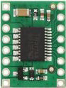
The Pololu TB6612FNG Motor Driver is a compact and efficient motor driver capable of controlling two DC motors or one stepper motor. It allows for precise control of motor direction and speed using PWM (Pulse Width Modulation) signals. This motor driver is widely used in robotics, automation, and other applications requiring motor control.
Explore Projects Built with Motor Driver 2 Channel

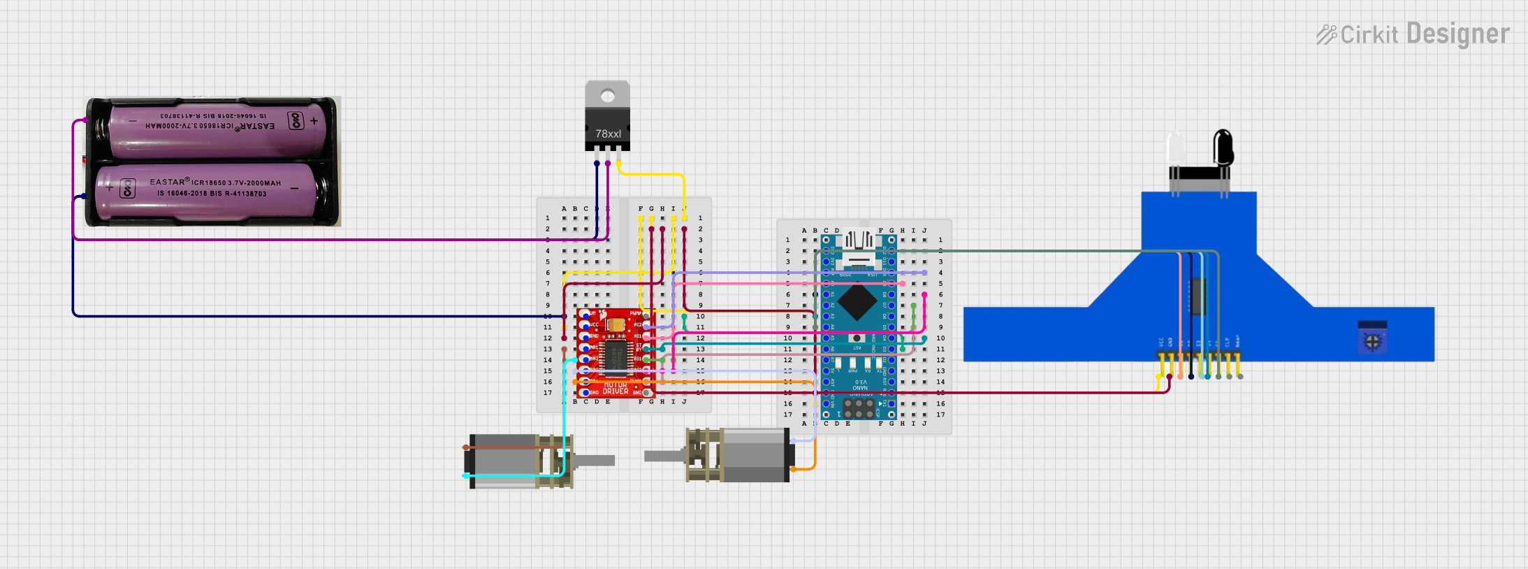

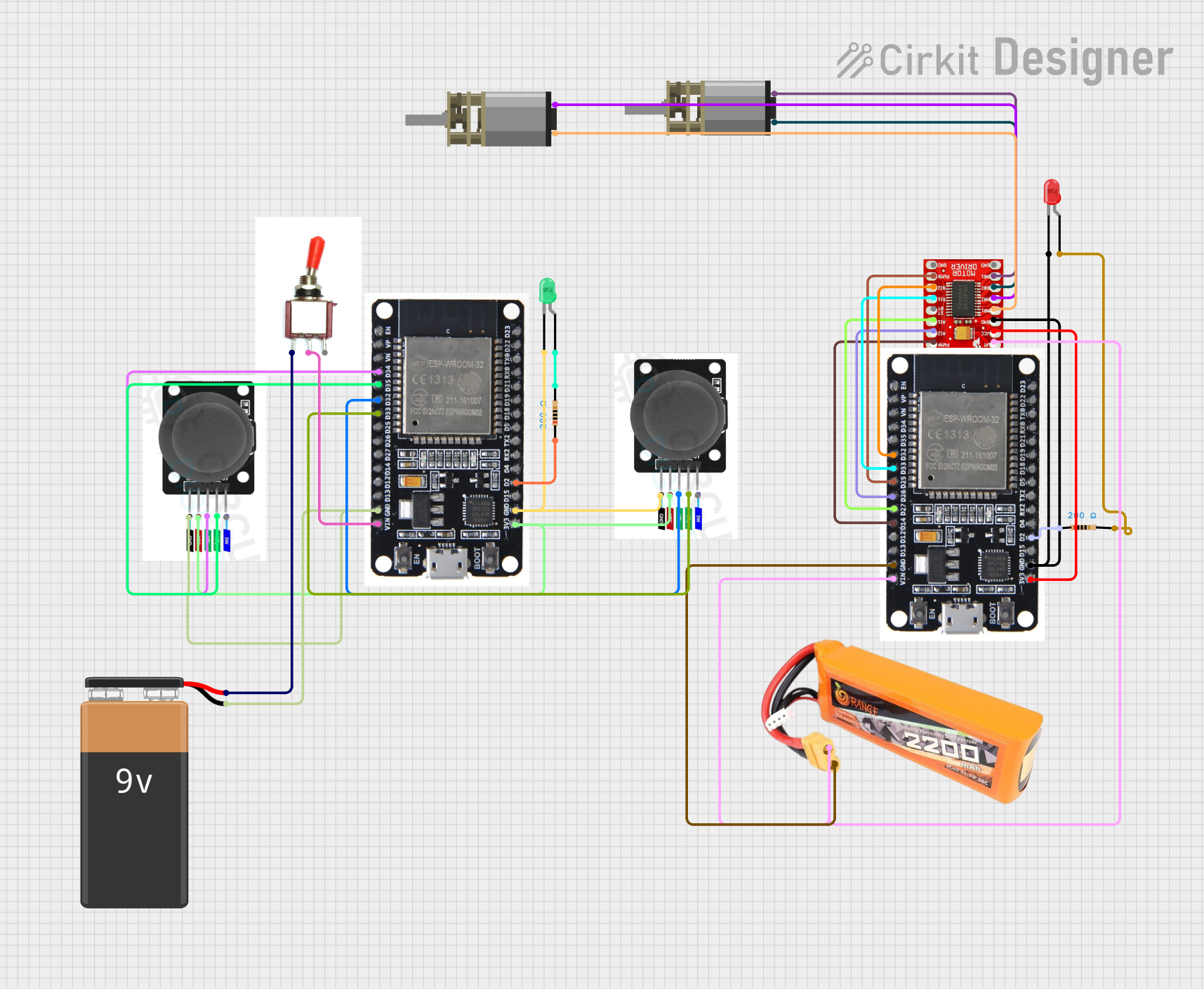
Explore Projects Built with Motor Driver 2 Channel
Common Applications
- Robotics (e.g., controlling wheels or arms)
- Automated conveyor systems
- Remote-controlled vehicles
- DIY electronics projects
- Stepper motor-based positioning systems
Technical Specifications
The following are the key technical details of the Pololu TB6612FNG motor driver:
| Parameter | Value |
|---|---|
| Operating Voltage | 2.7V to 5.5V |
| Motor Output Voltage | Up to 13.5V |
| Continuous Output Current | 1.2A per channel (3.2A peak) |
| Control Interface | PWM and digital signals |
| Logic Input Voltage | 2.7V to 5.5V |
| Standby Current | 1 µA (typical) |
| Dimensions | 18mm x 18mm x 3mm |
Pin Configuration and Descriptions
The TB6612FNG motor driver has 16 pins. Below is the pinout and description:
| Pin Name | Type | Description |
|---|---|---|
| VCC | Power Input | Logic voltage supply (2.7V to 5.5V). |
| VM | Power Input | Motor power supply (up to 13.5V). |
| GND | Ground | Ground connection for logic and motor power. |
| AIN1, AIN2 | Input | Control signals for Motor A direction. |
| BIN1, BIN2 | Input | Control signals for Motor B direction. |
| PWMA | PWM Input | Speed control for Motor A (PWM signal). |
| PWMB | PWM Input | Speed control for Motor B (PWM signal). |
| STBY | Input | Standby mode control (active low). |
| AO1, AO2 | Output | Motor A outputs. Connect to Motor A terminals. |
| BO1, BO2 | Output | Motor B outputs. Connect to Motor B terminals. |
| NC | - | No connection. |
| VCC2 | Power Input | Optional secondary logic voltage input (typically tied to VCC). |
Usage Instructions
How to Use the Component in a Circuit
Power Connections:
- Connect the VCC pin to a 3.3V or 5V logic power supply.
- Connect the VM pin to the motor power supply (e.g., 6V or 12V, depending on your motor).
- Connect the GND pin to the ground of both the logic and motor power supplies.
Motor Connections:
- Connect the motor terminals to AO1/AO2 for Motor A and BO1/BO2 for Motor B.
Control Signals:
- Use AIN1/AIN2 and BIN1/BIN2 to set the direction of Motor A and Motor B, respectively.
- Apply PWM signals to PWMA and PWMB to control the speed of Motor A and Motor B.
Standby Mode:
- Ensure the STBY pin is pulled high to enable the motor driver. Pulling it low will put the driver in standby mode.
Important Considerations and Best Practices
- Use appropriate decoupling capacitors (e.g., 0.1µF and 100µF) across the power supply lines to reduce noise.
- Ensure the motor's current draw does not exceed the driver's maximum ratings (1.2A continuous, 3.2A peak).
- Use heat sinks or proper ventilation if operating near the maximum current limits.
- Avoid leaving input pins floating; connect unused inputs to GND or VCC as needed.
Example: Connecting to an Arduino UNO
Below is an example of how to control two DC motors using the TB6612FNG motor driver and an Arduino UNO:
// Define motor control pins
const int AIN1 = 7;  // Motor A direction control pin 1
const int AIN2 = 8;  // Motor A direction control pin 2
const int PWMA = 9;  // Motor A speed control (PWM)
const int BIN1 = 10; // Motor B direction control pin 1
const int BIN2 = 11; // Motor B direction control pin 2
const int PWMB = 3;  // Motor B speed control (PWM)
const int STBY = 12; // Standby control pin

void setup() {
  // Set control pins as outputs
  pinMode(AIN1, OUTPUT);
  pinMode(AIN2, OUTPUT);
  pinMode(PWMA, OUTPUT);
  pinMode(BIN1, OUTPUT);
  pinMode(BIN2, OUTPUT);
  pinMode(PWMB, OUTPUT);
  pinMode(STBY, OUTPUT);

  // Enable the motor driver
  digitalWrite(STBY, HIGH);
}

void loop() {
  // Example: Run Motor A forward at 50% speed
  digitalWrite(AIN1, HIGH);
  digitalWrite(AIN2, LOW);
  analogWrite(PWMA, 128); // 50% duty cycle (0-255)

  // Example: Run Motor B backward at 75% speed
  digitalWrite(BIN1, LOW);
  digitalWrite(BIN2, HIGH);
  analogWrite(PWMB, 192); // 75% duty cycle (0-255)

  delay(2000); // Run for 2 seconds

  // Stop both motors
  analogWrite(PWMA, 0);
  analogWrite(PWMB, 0);

  delay(2000); // Wait for 2 seconds
}
Troubleshooting and FAQs
Common Issues and Solutions
Motors Not Running:
- Ensure the STBY pin is pulled high.
- Verify that the motor power supply (VM) is connected and within the specified range.
- Check the PWM signal connections and ensure the duty cycle is not set to 0.
Overheating:
- Ensure the motor's current draw does not exceed the driver's maximum ratings.
- Use heat sinks or improve ventilation if operating near the maximum current limits.
Erratic Motor Behavior:
- Check for loose or incorrect wiring.
- Add decoupling capacitors to the power supply lines to reduce noise.
Arduino Code Not Working:
- Verify that the pin numbers in the code match your wiring.
- Ensure the Arduino is powered and properly connected to the motor driver.
FAQs
Q: Can I use this driver with a 24V motor?
A: No, the maximum motor voltage (VM) is 13.5V. Using a higher voltage may damage the driver.
Q: Can I control a stepper motor with this driver?
A: Yes, the TB6612FNG can control a bipolar stepper motor by using both channels. You will need to generate the appropriate step and direction signals.
Q: What happens if I leave the STBY pin floating?
A: The motor driver will remain in standby mode, and the motors will not operate. Always pull the STBY pin high to enable the driver.