How to Use DIGITAL TO ANAOLG MODULE DAC: Examples, Pinouts, and Specs
Introduction
The DFROBOT DFR0552 Digital to Analog Converter (DAC) Module is a versatile and reliable component designed to convert digital signals (binary data) into analog signals (continuous voltage or current). This module is essential for applications where digital devices, such as microcontrollers or microprocessors, need to interface with analog systems like audio equipment, sensors, or actuators.
Explore Projects Built with DIGITAL TO ANAOLG MODULE DAC
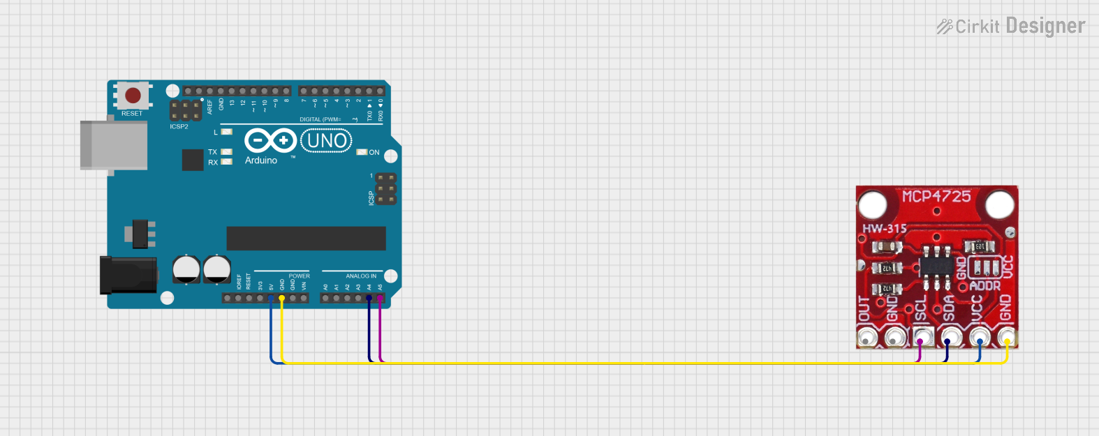


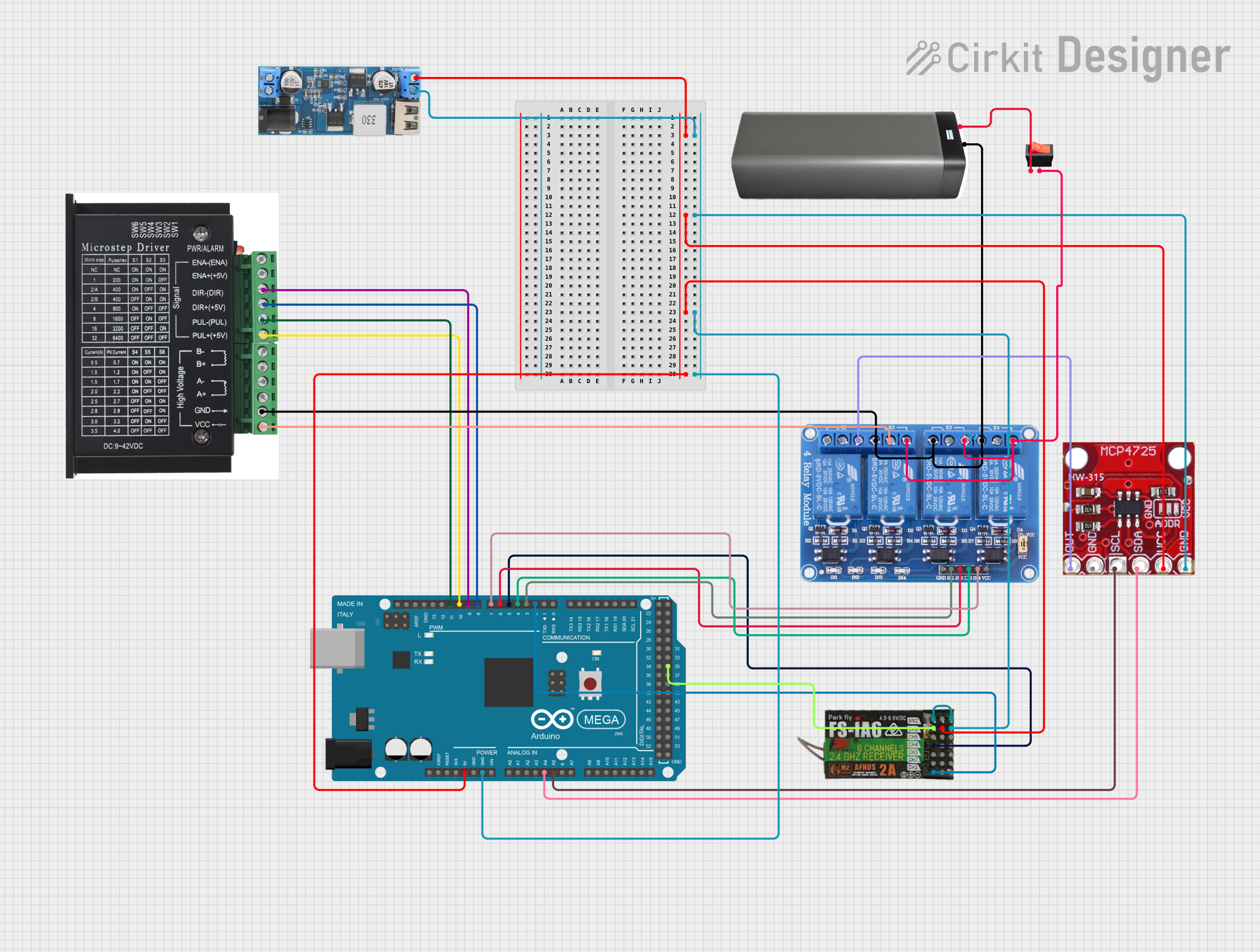
Explore Projects Built with DIGITAL TO ANAOLG MODULE DAC
Common Applications and Use Cases
- Audio signal generation and processing
- Analog control of motors, actuators, or other devices
- Signal reconstruction in communication systems
- Interfacing digital microcontrollers with analog sensors
- Generating reference voltages for testing and calibration
Technical Specifications
The following table outlines the key technical details of the DFR0552 DAC Module:
| Parameter | Specification |
|---|---|
| Manufacturer | DFRobot |
| Part ID | DFR0552 |
| Input Voltage | 3.3V to 5V DC |
| Output Voltage Range | 0V to 3.3V (or 0V to 5V, depending on input voltage) |
| Resolution | 12-bit (4096 discrete levels) |
| Communication Protocol | I2C |
| I2C Address | 0x48 (default, configurable) |
| Operating Temperature | -40°C to 85°C |
| Dimensions | 22mm x 32mm |
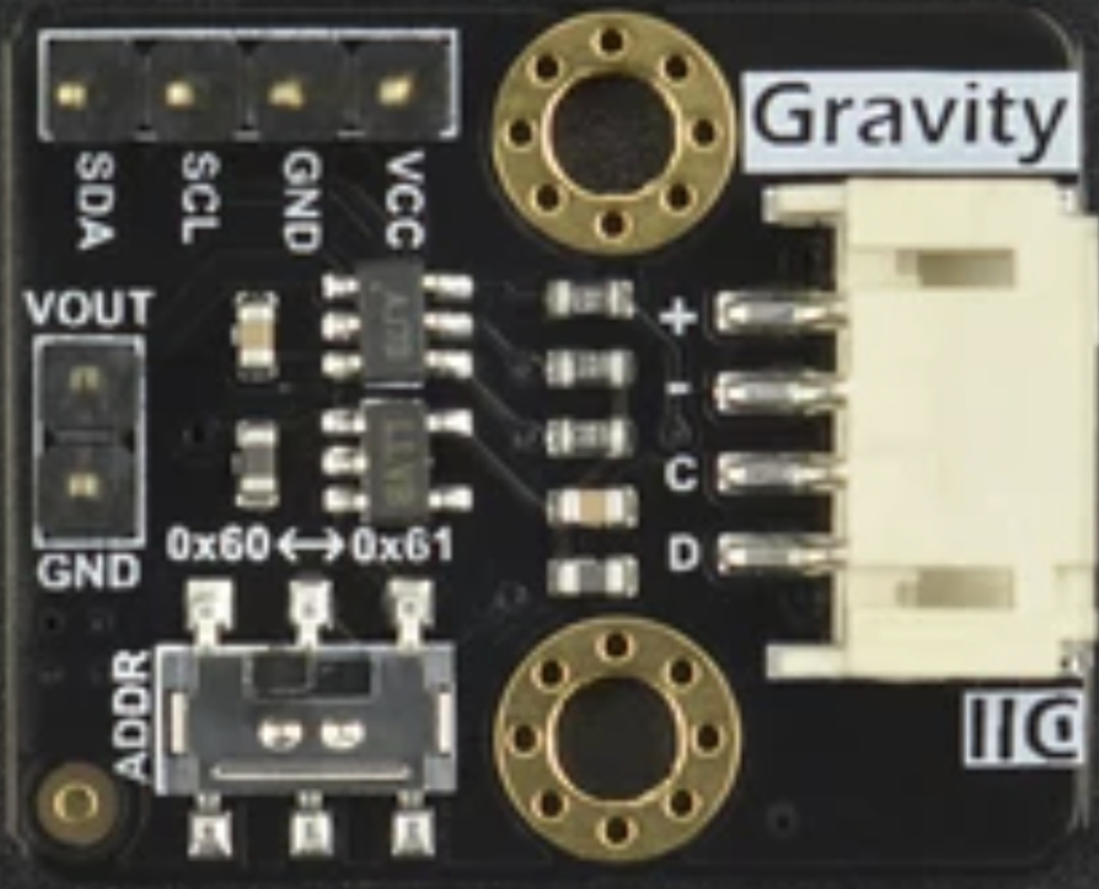
Pin Configuration and Descriptions
The DFR0552 DAC Module has the following pin layout:
| Pin | Name | Description |
|---|---|---|
| 1 | VCC | Power supply input (3.3V or 5V DC) |
| 2 | GND | Ground connection |
| 3 | SDA | I2C data line for communication with the microcontroller |
| 4 | SCL | I2C clock line for communication with the microcontroller |
| 5 | OUT | Analog output signal (voltage corresponding to the digital input) |
| 6 | ADDR | I2C address configuration pin (used to set a custom I2C address if necessary) |
Usage Instructions
How to Use the Component in a Circuit
- Power the Module: Connect the
VCCpin to a 3.3V or 5V power source and theGNDpin to the ground of your circuit. - Connect to a Microcontroller: Use the
SDAandSCLpins to connect the module to the I2C bus of your microcontroller (e.g., Arduino UNO). - Configure the I2C Address: If multiple I2C devices are used, configure the
ADDRpin to set a unique I2C address for the DAC module. - Read/Write Data: Send digital data to the DAC module via the I2C interface. The module will convert the digital input into an analog voltage output on the
OUTpin.
Important Considerations and Best Practices
- Ensure the power supply voltage matches the module's input voltage range (3.3V or 5V).
- Use pull-up resistors (typically 4.7kΩ) on the
SDAandSCLlines if not already present in your circuit. - Avoid exceeding the maximum output current of the DAC module to prevent damage.
- For precise analog output, ensure the digital input values are scaled correctly based on the module's resolution (12-bit).
Example: Using the DFR0552 DAC Module with Arduino UNO
Below is an example Arduino sketch to generate an analog voltage using the DFR0552 DAC module:
#include <Wire.h> // Include the Wire library for I2C communication

#define DAC_I2C_ADDRESS 0x48 // Default I2C address of the DFR0552 DAC module

void setup() {
  Wire.begin(); // Initialize I2C communication
  Serial.begin(9600); // Initialize serial communication for debugging
}

void loop() {
  uint16_t digitalValue = 2048; // Example digital value (12-bit: 0 to 4095)

  // Send the digital value to the DAC module
  Wire.beginTransmission(DAC_I2C_ADDRESS); // Start communication with DAC
  Wire.write(digitalValue >> 8); // Send the high byte of the 12-bit value
  Wire.write(digitalValue & 0xFF); // Send the low byte of the 12-bit value
  Wire.endTransmission(); // End communication

  Serial.print("Analog output set to: ");
  Serial.println(digitalValue * (5.0 / 4095.0)); // Print the corresponding voltage

  delay(1000); // Wait for 1 second before updating the output
}
Notes:
- Replace
5.0in the voltage calculation with3.3if the module is powered by a 3.3V source. - Adjust the
digitalValuevariable to generate different analog output voltages.
Troubleshooting and FAQs
Common Issues and Solutions
No Output Signal on the OUT Pin:
- Verify that the module is powered correctly (check
VCCandGNDconnections). - Ensure the I2C address matches the one configured in your code.
- Check the
SDAandSCLconnections for proper communication.
- Verify that the module is powered correctly (check
Incorrect Output Voltage:
- Confirm that the digital input value is within the valid range (0 to 4095 for 12-bit resolution).
- Ensure the power supply voltage matches the expected range (3.3V or 5V).
I2C Communication Errors:
- Use pull-up resistors on the
SDAandSCLlines if not already present. - Check for address conflicts if multiple I2C devices are connected.
- Use pull-up resistors on the
FAQs
Q: Can the DFR0552 DAC module output negative voltages?
A: No, the module outputs voltages in the range of 0V to the supply voltage (3.3V or 5V).
Q: How do I change the I2C address of the module?
A: Use the ADDR pin to configure a custom I2C address. Refer to the module's datasheet for specific instructions.
Q: What is the maximum current the module can drive?
A: The module is designed for low-current applications. For higher current requirements, use a buffer or amplifier circuit.
Q: Can I use this module with a Raspberry Pi?
A: Yes, the module is compatible with any device that supports I2C communication, including Raspberry Pi.
By following this documentation, you can effectively integrate the DFR0552 DAC Module into your projects and achieve precise digital-to-analog signal conversion.