How to Use dc TO dC STEP UP: Examples, Pinouts, and Specs
Introduction
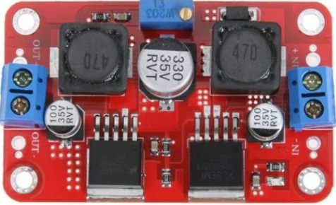
A DC to DC step-up converter, also known as a boost converter, is an electronic circuit designed to increase the input voltage to a higher output voltage while maintaining the same current direction. This component is widely used in applications where a higher voltage is required from a lower voltage source, such as in battery-powered devices, renewable energy systems, and portable electronics.
Explore Projects Built with dc TO dC STEP UP


Explore Projects Built with dc TO dC STEP UP
Common Applications and Use Cases
- Powering high-voltage devices from low-voltage batteries
- Solar power systems to step up panel voltage
- LED drivers for high-power LEDs
- Electric vehicles and hybrid systems
- Portable power banks and chargers
Technical Specifications
Below are the key technical details for a typical DC to DC step-up converter. Note that specific values may vary depending on the model and manufacturer.
General Specifications
| Parameter | Value |
|---|---|
| Input Voltage Range | 3V to 32V |
| Output Voltage Range | 5V to 35V |
| Maximum Output Current | 2A to 5A (depending on the model) |
| Efficiency | Up to 95% |
| Switching Frequency | 150 kHz |
| Operating Temperature | -40°C to +85°C |
Pin Configuration and Descriptions
| Pin Name | Description |
|---|---|
| VIN | Input voltage pin. Connect the lower voltage source here. |
| GND | Ground pin. Connect to the ground of the input and output circuits. |
| VOUT | Output voltage pin. Provides the boosted voltage to the load. |
| EN | Enable pin. Used to turn the converter on or off (optional, depending on model). |
Usage Instructions
How to Use the Component in a Circuit
Connect the Input Voltage Source:
- Attach the positive terminal of the input voltage source to the
VINpin. - Connect the negative terminal of the input source to the
GNDpin.
- Attach the positive terminal of the input voltage source to the
Connect the Load:
- Attach the positive terminal of the load to the
VOUTpin. - Connect the negative terminal of the load to the
GNDpin.
- Attach the positive terminal of the load to the
Adjust the Output Voltage (if applicable):
- Many step-up converters include a potentiometer to adjust the output voltage.
- Use a small screwdriver to turn the potentiometer clockwise to increase the voltage or counterclockwise to decrease it.
- Use a multimeter to measure the output voltage while adjusting.
Enable the Converter (if applicable):
- If the converter has an
ENpin, ensure it is connected to a high logic level (e.g., 3.3V or 5V) to enable the circuit.
- If the converter has an
Important Considerations and Best Practices
- Input Voltage Range: Ensure the input voltage is within the specified range of the converter to avoid damage.
- Output Current Limit: Do not exceed the maximum output current rating, as this may cause overheating or failure.
- Heat Dissipation: For high-power applications, consider adding a heatsink or active cooling to prevent overheating.
- Ripple and Noise: Use appropriate capacitors at the input and output to reduce voltage ripple and noise.
- Polarity: Double-check the polarity of the connections to avoid damaging the converter.
Example: Using a DC to DC Step-Up Converter with Arduino UNO
Below is an example of how to use a DC to DC step-up converter to power an Arduino UNO from a 3.7V lithium-ion battery.
Circuit Connections
- Connect the positive terminal of the 3.7V battery to the
VINpin of the converter. - Connect the negative terminal of the battery to the
GNDpin of the converter. - Adjust the output voltage of the converter to 5V using the potentiometer.
- Connect the
VOUTpin of the converter to the5Vpin of the Arduino UNO. - Connect the
GNDpin of the converter to theGNDpin of the Arduino UNO.
Sample Code
// Example code to blink an LED connected to pin 13 of the Arduino UNO
// Ensure the Arduino is powered via the DC to DC step-up converter

void setup() {
  pinMode(13, OUTPUT); // Set pin 13 as an output pin
}

void loop() {
  digitalWrite(13, HIGH); // Turn the LED on
  delay(1000);            // Wait for 1 second
  digitalWrite(13, LOW);  // Turn the LED off
  delay(1000);            // Wait for 1 second
}
Troubleshooting and FAQs
Common Issues and Solutions
No Output Voltage:
- Check the input voltage and ensure it is within the specified range.
- Verify all connections, especially the polarity of the input and output.
- If the converter has an
ENpin, ensure it is enabled.
Output Voltage is Incorrect:
- Adjust the potentiometer to set the desired output voltage.
- Ensure the load does not exceed the maximum current rating.
Overheating:
- Reduce the load current if it exceeds the converter's capacity.
- Add a heatsink or active cooling to improve heat dissipation.
High Ripple or Noise:
- Add low ESR capacitors at the input and output terminals.
- Use shorter wires to minimize inductive noise.
FAQs
Q: Can I use a DC to DC step-up converter with a solar panel?
A: Yes, as long as the solar panel's output voltage is within the input range of the converter. Ensure the panel provides sufficient current for the load.
Q: What happens if I reverse the polarity of the input?
A: Most converters do not have reverse polarity protection and may be damaged. Always double-check the polarity before powering the circuit.
Q: Can I use this converter to charge a battery?
A: It is not recommended to directly charge a battery unless the converter includes a proper charging circuit. Use a dedicated battery charging module for this purpose.
Q: How do I calculate the efficiency of the converter?
A: Efficiency can be calculated using the formula:
[
\text{Efficiency} (%) = \left( \frac{\text{Output Power}}{\text{Input Power}} \right) \times 100
]
Measure the input and output voltage and current to determine the power values.
By following this documentation, you can effectively use a DC to DC step-up converter in your projects and troubleshoot common issues.