Cirkit Designer Logo
Cirkit Designer
Your all-in-one circuit design IDE
Home / 
Component Documentation

How to Use Adafruit ISO1540: Examples, Pinouts, and Specs

Image of Adafruit ISO1540
Cirkit Designer LogoDesign with Adafruit ISO1540 in Cirkit Designer

Introduction

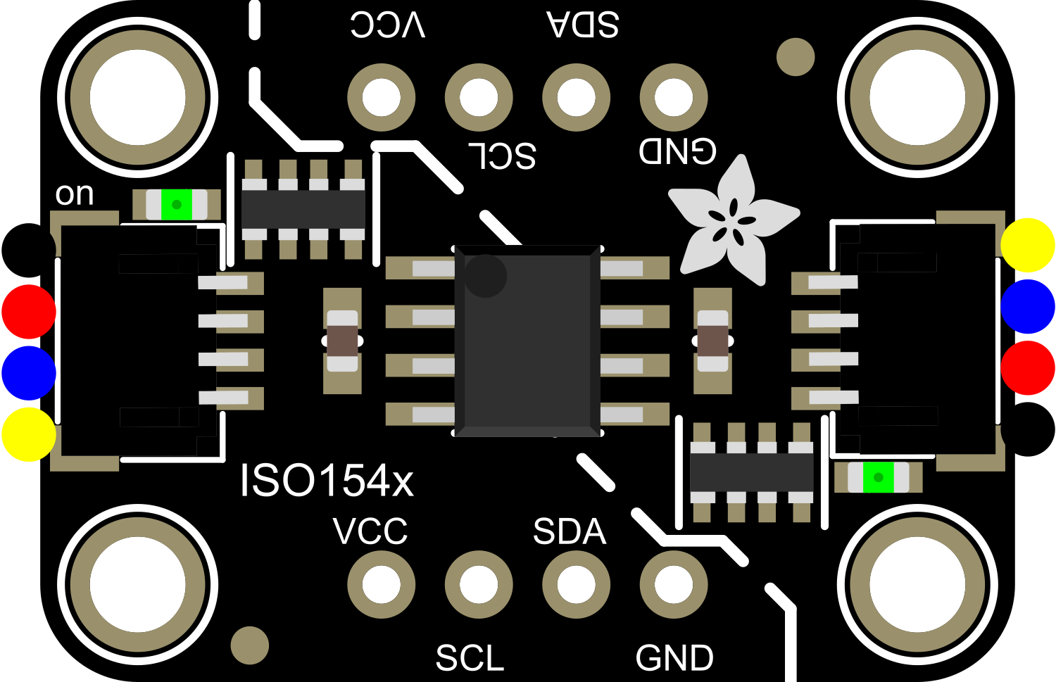
The Adafruit ISO1540 is a high-speed, bi-directional isolator that is designed to provide galvanic isolation between different parts of a circuit. This component is particularly useful in applications where sensitive components need to be protected from voltage spikes, electrical noise, or ground loop issues. It is commonly used in industrial automation systems, medical equipment, and any application requiring a robust communication interface with isolation.

Explore Projects Built with Adafruit ISO1540

Use Cirkit Designer to design, explore, and prototype these projects online. Some projects support real-time simulation. Click "Open Project" to start designing instantly!
Battery-Powered Smart Sensor Hub with Adafruit QT Py RP2040
Image of wearable final: A project utilizing Adafruit ISO1540 in a practical application
This circuit features an Adafruit QT Py RP2040 microcontroller interfaced with an APDS9960 proximity sensor, an MPU6050 accelerometer and gyroscope, and an OLED display via I2C communication. It also includes a buzzer controlled by the microcontroller and is powered by a 3.7V LiPo battery with a toggle switch for power control.
Cirkit Designer LogoOpen Project in Cirkit Designer
Battery-Powered Sensor Hub with Adafruit QT Py RP2040 and OLED Display
Image of 512: A project utilizing Adafruit ISO1540 in a practical application
This circuit features an Adafruit QT Py RP2040 microcontroller interfacing with an MPU-6050 accelerometer, an Adafruit APDS-9960 sensor, and a 0.96" OLED display via I2C communication. It is powered by a 3.7V LiPo battery and includes a green LED with a current-limiting resistor connected to an analog pin of the microcontroller.
Cirkit Designer LogoOpen Project in Cirkit Designer
ATmega328P-Based Sensor Hub with OLED Display and LIDAR
Image of TILTPCB: A project utilizing Adafruit ISO1540 in a practical application
This circuit features an Mtiny Uno ATmega328P microcontroller as its central processing unit, interfacing with a variety of sensors and peripherals. It includes a 0.96" OLED display and an MPU6050 accelerometer/gyroscope for user interface and motion sensing, respectively. The circuit also integrates a TF LUNA LIDAR for distance measurement, a DHT11 sensor for temperature and humidity readings, and uses a 9V battery with a 7805 voltage regulator for power management. Communication with a computer for programming and data exchange is facilitated by an Adafruit FTDI Friend module.
Cirkit Designer LogoOpen Project in Cirkit Designer
Battery-Powered Smart Light with Proximity Sensor and OLED Display using Adafruit QT Py RP2040
Image of lab: A project utilizing Adafruit ISO1540 in a practical application
This circuit is a portable, battery-powered system featuring an Adafruit QT Py RP2040 microcontroller that interfaces with an OLED display, a proximity sensor, an accelerometer, and an RGB LED strip. The system is powered by a lithium-ion battery with a step-up boost converter to provide 5V for the LED strip, and it includes a toggle switch for power control. The microcontroller communicates with the sensors and display via I2C.
Cirkit Designer LogoOpen Project in Cirkit Designer

Explore Projects Built with Adafruit ISO1540

Use Cirkit Designer to design, explore, and prototype these projects online. Some projects support real-time simulation. Click "Open Project" to start designing instantly!
Image of wearable final: A project utilizing Adafruit ISO1540 in a practical application
Battery-Powered Smart Sensor Hub with Adafruit QT Py RP2040
This circuit features an Adafruit QT Py RP2040 microcontroller interfaced with an APDS9960 proximity sensor, an MPU6050 accelerometer and gyroscope, and an OLED display via I2C communication. It also includes a buzzer controlled by the microcontroller and is powered by a 3.7V LiPo battery with a toggle switch for power control.
Cirkit Designer LogoOpen Project in Cirkit Designer
Image of 512: A project utilizing Adafruit ISO1540 in a practical application
Battery-Powered Sensor Hub with Adafruit QT Py RP2040 and OLED Display
This circuit features an Adafruit QT Py RP2040 microcontroller interfacing with an MPU-6050 accelerometer, an Adafruit APDS-9960 sensor, and a 0.96" OLED display via I2C communication. It is powered by a 3.7V LiPo battery and includes a green LED with a current-limiting resistor connected to an analog pin of the microcontroller.
Cirkit Designer LogoOpen Project in Cirkit Designer
Image of TILTPCB: A project utilizing Adafruit ISO1540 in a practical application
ATmega328P-Based Sensor Hub with OLED Display and LIDAR
This circuit features an Mtiny Uno ATmega328P microcontroller as its central processing unit, interfacing with a variety of sensors and peripherals. It includes a 0.96" OLED display and an MPU6050 accelerometer/gyroscope for user interface and motion sensing, respectively. The circuit also integrates a TF LUNA LIDAR for distance measurement, a DHT11 sensor for temperature and humidity readings, and uses a 9V battery with a 7805 voltage regulator for power management. Communication with a computer for programming and data exchange is facilitated by an Adafruit FTDI Friend module.
Cirkit Designer LogoOpen Project in Cirkit Designer
Image of lab: A project utilizing Adafruit ISO1540 in a practical application
Battery-Powered Smart Light with Proximity Sensor and OLED Display using Adafruit QT Py RP2040
This circuit is a portable, battery-powered system featuring an Adafruit QT Py RP2040 microcontroller that interfaces with an OLED display, a proximity sensor, an accelerometer, and an RGB LED strip. The system is powered by a lithium-ion battery with a step-up boost converter to provide 5V for the LED strip, and it includes a toggle switch for power control. The microcontroller communicates with the sensors and display via I2C.
Cirkit Designer LogoOpen Project in Cirkit Designer

Common Applications and Use Cases

  • Isolating microcontroller interfaces
  • Breaking ground loops in communication systems
  • Protecting against voltage spikes in power supplies
  • Noise reduction in sensitive signal measurements
  • Ensuring safety in medical device communications

Technical Specifications

Key Technical Details

  • Isolation Voltage: 2500 Vrms (1 minute)
  • Data Rates: Up to 1 Mbps
  • Operating Voltage Range: 2.25 V to 5.5 V
  • Operating Temperature Range: -40°C to +125°C
  • Package: SOIC-8

Pin Configuration and Descriptions

Pin Number Name Description
1 VCC1 Power supply for the input side (2.25 V to 5.5 V)
2 GND1 Ground reference for the input side
3 SDA1 Serial Data Line for input side
4 SCL1 Serial Clock Line for input side
5 SCL2 Serial Clock Line for output side
6 SDA2 Serial Data Line for output side
7 GND2 Ground reference for the output side
8 VCC2 Power supply for the output side (2.25 V to 5.5 V)

Usage Instructions

How to Use the Component in a Circuit

  1. Power Connections: Connect VCC1 and GND1 to the power supply of the input side of the circuit. Similarly, connect VCC2 and GND2 to the power supply of the output side of the circuit.
  2. Data Connections: Connect SDA1 and SCL1 to the I2C data and clock lines of the input side microcontroller. Connect SDA2 and SCL2 to the I2C data and clock lines of the output side microcontroller or device.
  3. Isolation: Ensure that there is no electrical connection between the ground or power supply of the input and output sides to maintain proper isolation.

Important Considerations and Best Practices

  • Always verify that the power supply voltage levels on both sides of the isolator are within the specified operating range.
  • Keep the traces or wires between the ISO1540 and the microcontrollers as short as possible to minimize signal degradation.
  • Avoid running high-voltage or high-current lines parallel and close to the ISO1540 communication lines to prevent interference.
  • Ensure that the isolator is placed on a clean, dry, and non-conductive surface to maintain isolation integrity.

Troubleshooting and FAQs

Common Issues Users Might Face

  • Communication Failure: Ensure that the I2C lines are connected correctly and that there are pull-up resistors on both SDA and SCL lines as required by the I2C specification.
  • Unexpected Resets: Check for proper power supply decoupling with capacitors close to the VCC and GND pins of the ISO1540 to prevent voltage spikes from causing resets.

Solutions and Tips for Troubleshooting

  • If communication is not working, verify that the isolator is powered on both sides and that the I2C bus is not being held low by any device.
  • Use an oscilloscope to check the integrity of the I2C signals. Look for clean transitions and the absence of excessive noise.
  • Ensure that the isolator is not being exposed to voltages beyond its absolute maximum ratings, as this can cause permanent damage.

FAQs

Q: Can the ISO1540 be used with different voltages on each side? A: Yes, the ISO1540 can support different voltages on each side as long as they are within the 2.25 V to 5.5 V range.

Q: Is the ISO1540 compatible with standard I2C protocols? A: Yes, the ISO1540 is designed to be compatible with standard I2C protocols and can support data rates up to 1 Mbps.

Q: Does the ISO1540 require any external components? A: The ISO1540 typically requires pull-up resistors on the SDA and SCL lines, as per I2C specifications. Decoupling capacitors on the power supply lines are also recommended.

Example Arduino UNO Connection and Code

Connection to Arduino UNO

  • Connect VCC1 to Arduino 5V and GND1 to Arduino GND.
  • Connect SDA1 and SCL1 to Arduino A4 (SDA) and A5 (SCL), respectively.
  • Connect VCC2 to the secondary device's power supply and GND2 to its ground.
  • Connect SDA2 and SCL2 to the secondary device's I2C data and clock lines.

Sample Arduino Code

#include <Wire.h>

void setup() {
  Wire.begin(); // Join the I2C bus as a master
  Serial.begin(9600); // Start serial communication at 9600 baud
}

void loop() {
  Wire.beginTransmission(0x50); // Begin transmission to a device with address 0x50
  Wire.write(0x00); // Write a byte to the I2C bus
  Wire.endTransmission(); // End transmission

  delay(1000); // Wait for 1000 milliseconds

  Wire.requestFrom(0x50, 1); // Request 1 byte from the device with address 0x50
  while (Wire.available()) { // While there is a byte to receive
    char c = Wire.read(); // Read a byte
    Serial.println(c); // Print the byte to the Serial monitor
  }

  delay(1000); // Wait for 1000 milliseconds
}

Note: The above code is a basic example to demonstrate communication with a device on the other side of the ISO1540. The actual implementation will depend on the specific device and its I2C address. Always refer to the device's datasheet for correct addressing and commands.