How to Use Adafruit PCA9546 : Examples, Pinouts, and Specs
Introduction
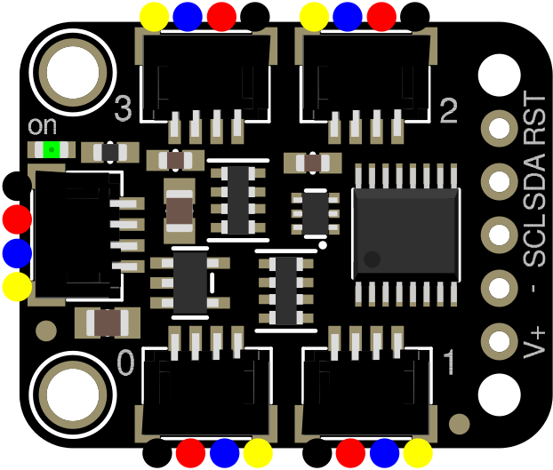
The Adafruit PCA9546 is an I2C multiplexer designed to simplify the connection of multiple I2C devices to a single I2C bus. It allows users to select one of four downstream I2C buses, enabling the management of devices with identical I2C addresses. This component is particularly useful in applications where multiple sensors or modules with the same address need to coexist on the same system.
Explore Projects Built with Adafruit PCA9546
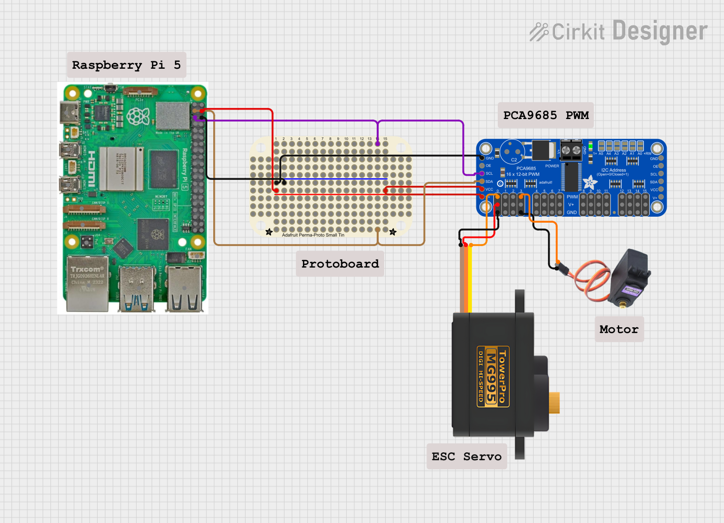
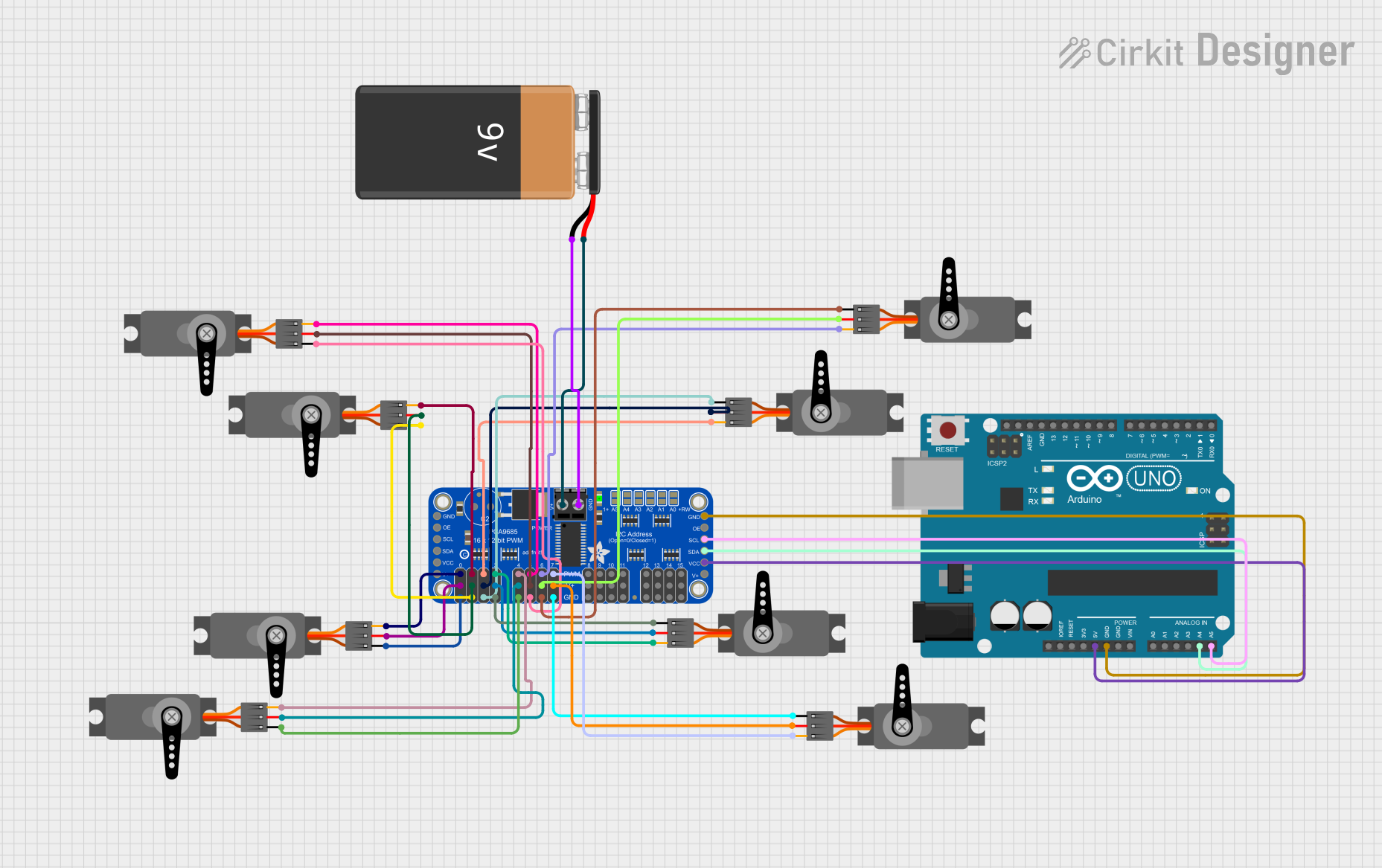
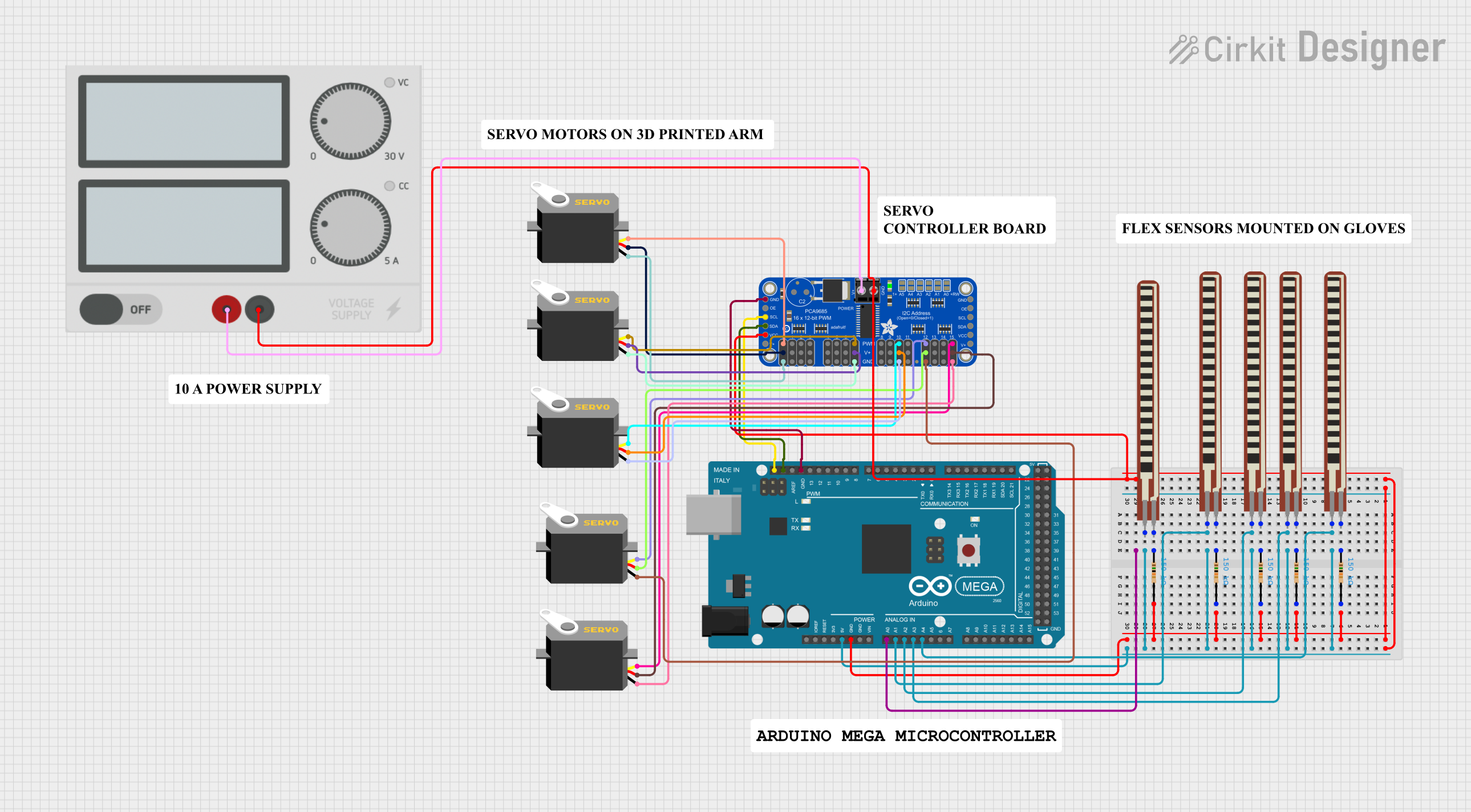
Explore Projects Built with Adafruit PCA9546
Common Applications and Use Cases
- Managing multiple I2C devices with identical addresses
- Expanding the number of I2C devices on a single bus
- Prototyping and testing I2C devices
- Applications in robotics, IoT, and sensor networks
Technical Specifications
- Operating Voltage: 1.8V to 5.5V
- I2C Address: 0x70 (default, configurable via address pins)
- Number of Channels: 4 downstream I2C buses
- Maximum I2C Clock Frequency: 400 kHz (Fast Mode)
- Current Consumption: ~1 µA (standby), ~2 mA (active)
- Operating Temperature Range: -40°C to +85°C
- Package Type: SOIC-16 (on breakout board)
Pin Configuration and Descriptions
| Pin | Name | Description |
|---|---|---|
| 1 | A0 | Address selection pin (LSB). Connect to GND or VCC to set I2C address. |
| 2 | A1 | Address selection pin. Connect to GND or VCC to set I2C address. |
| 3 | A2 | Address selection pin (MSB). Connect to GND or VCC to set I2C address. |
| 4 | GND | Ground connection. |
| 5 | SDA | I2C data line (shared upstream). |
| 6 | SCL | I2C clock line (shared upstream). |
| 7-10 | SD0-SD3 | I2C data lines for downstream buses 0-3. |
| 11-14 | SC0-SC3 | I2C clock lines for downstream buses 0-3. |
| 15 | RESET | Active-low reset pin. Pull low to reset the multiplexer. |
| 16 | VCC | Power supply input (1.8V to 5.5V). |
Usage Instructions
How to Use the Component in a Circuit
- Power the PCA9546: Connect the VCC pin to a power source (1.8V to 5.5V) and the GND pin to ground.
- Set the I2C Address: Configure the A0, A1, and A2 pins to set the desired I2C address. These pins can be connected to GND (logic 0) or VCC (logic 1).
- Connect the I2C Bus: Attach the upstream I2C bus to the SDA and SCL pins. Connect the downstream I2C devices to the appropriate SDx and SCx pins.
- Control the Multiplexer: Use I2C commands to select the desired downstream bus. Only one bus can be active at a time.
Important Considerations and Best Practices
- Pull-Up Resistors: Ensure that appropriate pull-up resistors are present on the SDA and SCL lines. The PCA9546 does not include internal pull-ups.
- Bus Voltage Compatibility: The PCA9546 supports level translation between 1.8V and 5.5V. Ensure that the voltage levels of the upstream and downstream buses are compatible.
- Reset Pin: Use the RESET pin to reset the multiplexer if needed. This can be useful in case of communication issues.
- I2C Address Conflicts: Avoid address conflicts by carefully configuring the A0, A1, and A2 pins.
Example Code for Arduino UNO
The following example demonstrates how to use the Adafruit PCA9546 with an Arduino UNO to select a downstream bus and communicate with a device.
#include <Wire.h>

// Define the I2C address of the PCA9546 (default is 0x70)
#define PCA9546_ADDR 0x70

void setup() {
  Wire.begin(); // Initialize I2C communication
  Serial.begin(9600); // Start serial communication for debugging

  // Select downstream bus 0
  selectBus(0);
  Serial.println("Bus 0 selected");

  // Example: Communicate with a device on bus 0
  Wire.beginTransmission(0x40); // Replace 0x40 with the device's I2C address
  Wire.write(0x00); // Example: Write a command or register address
  Wire.endTransmission();
}

void loop() {
  // Add your main code here
}

// Function to select a downstream bus
void selectBus(uint8_t bus) {
  if (bus > 3) {
    Serial.println("Invalid bus number! Must be 0-3.");
    return;
  }

  Wire.beginTransmission(PCA9546_ADDR);
  Wire.write(1 << bus); // Write the control byte to select the bus
  Wire.endTransmission();
}
Troubleshooting and FAQs
Common Issues and Solutions
I2C Devices Not Responding
- Cause: Incorrect bus selection or I2C address conflict.
- Solution: Verify the selected bus and ensure no address conflicts exist.
Communication Errors
- Cause: Missing or incorrect pull-up resistors on the I2C lines.
- Solution: Add appropriate pull-up resistors (typically 4.7kΩ) to the SDA and SCL lines.
Multiplexer Not Responding
- Cause: Incorrect I2C address configuration.
- Solution: Check the A0, A1, and A2 pin connections and ensure the correct address is used in the code.
Downstream Devices Not Detected
- Cause: Voltage level mismatch between the upstream and downstream buses.
- Solution: Ensure that the voltage levels of all connected devices are compatible.
FAQs
Can I activate multiple buses simultaneously? No, the PCA9546 allows only one downstream bus to be active at a time.
What happens if the RESET pin is left floating? The RESET pin has an internal pull-up resistor, so it can be left unconnected if not used.
Can the PCA9546 be used with 3.3V and 5V devices on the same bus? Yes, the PCA9546 supports level translation, but ensure that the voltage levels are within the supported range (1.8V to 5.5V).