How to Use OV2640 Camera Module: Examples, Pinouts, and Specs
Introduction
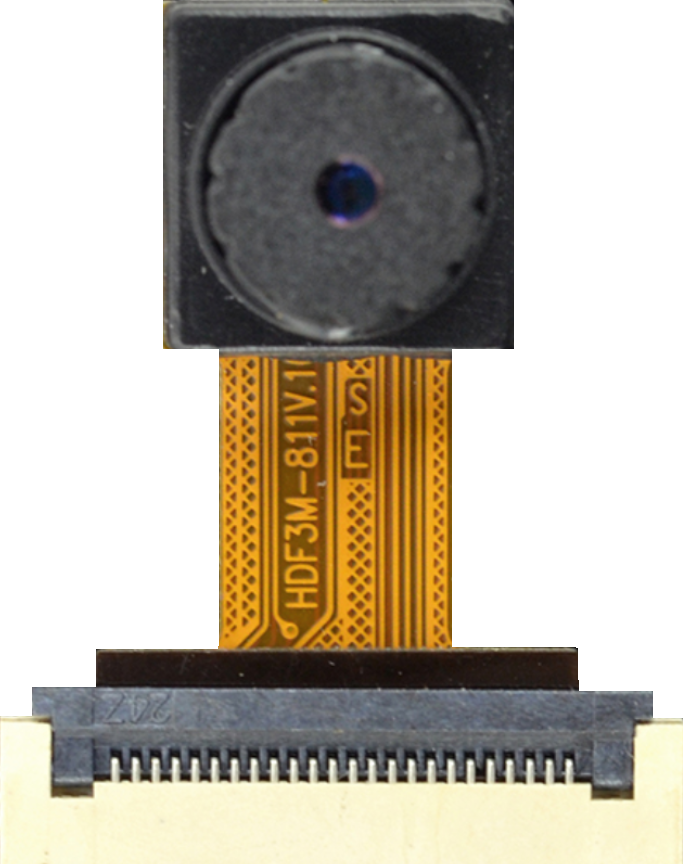
The OV2640 Camera Module is a popular imaging solution for embedded systems and Internet of Things (IoT) applications. This 2-megapixel camera module is capable of capturing high-resolution still images and streaming video at various frame rates. It is widely used in applications such as surveillance systems, robotics, and DIY projects. The module interfaces with microcontrollers and microprocessors through I2C and SPI communication protocols, offering flexibility in system design.
Explore Projects Built with OV2640 Camera Module

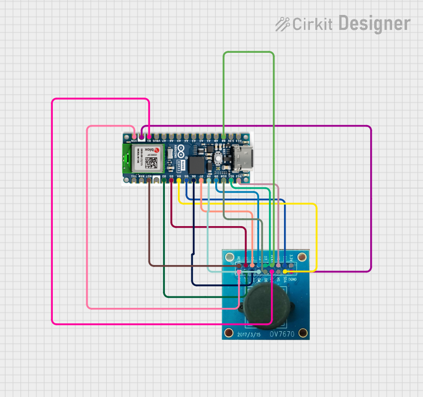
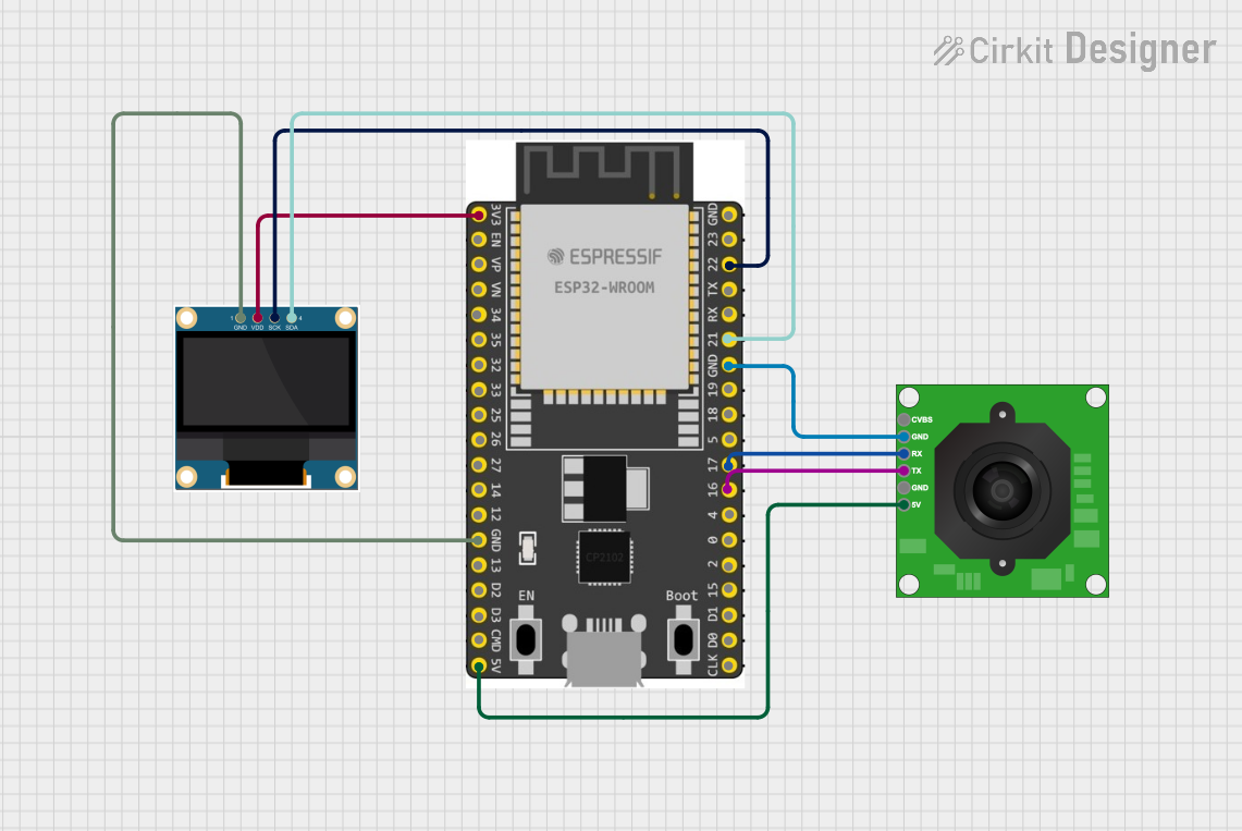
Explore Projects Built with OV2640 Camera Module
Technical Specifications
Key Features
- Resolution: 2 Megapixels
- Sensor Type: CMOS
- Output Formats: YUV(422/420)/YCbCr422, RGB565/555, 8-bit compressed data, 8-/10-bit Raw RGB data
- Lens Size: 1/4 inch
- Max Frame Rate: 15 fps at 1600x1200 UXGA, 30 fps at 800x600 SVGA
- Sensitivity: 1.3V / (Lux-sec)
- Signal to Noise Ratio: 40 dB
- Dynamic Range: 50 dB
- View Angle: 60 degrees
- Operating Voltage: 3.3V
- Operating Temperature: -30°C to 70°C
Pin Configuration and Descriptions
| Pin Number | Pin Name | Description |
|---|---|---|
| 1 | VCC | Power supply (3.3V) |
| 2 | GND | Ground connection |
| 3 | SIOC | I2C Clock |
| 4 | SIOD | I2C Data |
| 5 | VSYNC | Vertical synchronization |
| 6 | HREF | Horizontal reference signal |
| 7 | PCLK | Pixel Clock |
| 8 | XCLK | System Clock |
| 9 | D2 | Data bit 2 |
| 10 | D3 | Data bit 3 |
| 11 | D4 | Data bit 4 |
| 12 | D5 | Data bit 5 |
| 13 | D6 | Data bit 6 |
| 14 | D7 | Data bit 7 |
| 15 | D8 | Data bit 8 |
| 16 | D9 | Data bit 9 |
| 17 | RESET | Reset signal (active low) |
| 18 | PWDN | Power down mode |
Usage Instructions
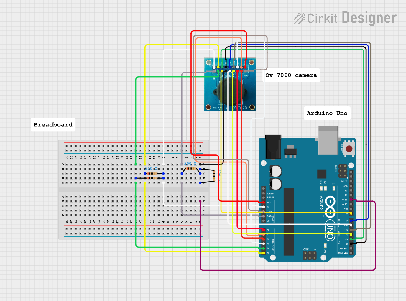
Integration with Arduino UNO
To use the OV2640 Camera Module with an Arduino UNO, follow these steps:
Connection: Connect the camera module to the Arduino UNO using the appropriate pins. Ensure that the VCC and GND are connected to the 3.3V and GND pins on the Arduino, respectively.
Library Installation: Install the necessary libraries to interface with the camera module. Libraries such as the ArduCAM library can be used for this purpose.
Initialization: Initialize the camera module in your Arduino sketch, setting up the correct image format and resolution.
Capture: Write code to capture images or video frames from the camera module.
Processing: Process the captured images or video frames as required for your application.
Display/Store: Display the images on a screen or store them on a memory device if needed.
Example Code
#include <ArduCAM.h>
#include <SPI.h>
#include <Wire.h>
// This example is designed to work with the OV2640 camera module.

// Select the correct camera module:
#define OV2640_MINI_2MP
#include <memorysaver.h>

// Set up the camera model and I2C pins
ArduCAM myCAM(OV2640, A4, A5);

void setup() {
  uint8_t vid, pid;
  uint8_t temp;

  Wire.begin();
  Serial.begin(115200);
  Serial.println(F("OV2640 Camera Module Test"));
  // Check if the ArduCAM SPI bus is OK
  myCAM.write_reg(ARDUCHIP_TEST1, 0x55);
  temp = myCAM.read_reg(ARDUCHIP_TEST1);
  if (temp != 0x55) {
    Serial.println(F("SPI interface Error!"));
    while (1);
  }

  // Initialize the camera module
  myCAM.InitCAM();
  myCAM.set_format(JPEG);
  myCAM.InitCAM();
  myCAM.OV2640_set_JPEG_size(OV2640_320x240);

  delay(1000);
}

void loop() {
  // Capture an image and store it to the SD/TF card
  // The actual implementation will depend on your specific requirements
}
Note: The above code is a basic example to demonstrate how to initialize the camera module. You will need to implement the capture and storage mechanisms based on your project's requirements.
Troubleshooting and FAQs
Common Issues
- No Image Captured: Ensure that the camera module is correctly powered and that all connections are secure. Check the initialization code for correct settings.
- Poor Image Quality: Adjust the focus of the camera lens. Ensure that the lighting conditions are adequate for the camera module.
- Communication Errors: Verify that the I2C and SPI connections are correct and that there are no loose connections.
FAQs
Q: Can the OV2640 Camera Module be used with other microcontrollers besides Arduino? A: Yes, the OV2640 can be interfaced with various microcontrollers that support I2C and SPI communication protocols.
Q: What is the maximum resolution of the OV2640 Camera Module? A: The maximum resolution is 1600x1200 UXGA.
Q: How do I change the image format to JPEG?
A: You can change the image format by using the myCAM.set_format(JPEG); function in your code.
Q: Is it possible to stream video with the OV2640 Camera Module? A: Yes, the module is capable of streaming video at various frame rates depending on the resolution.
Q: How do I focus the camera lens? A: The lens can be manually focused by rotating it until the desired focus is achieved.
For further assistance, consult the manufacturer's datasheet and the community forums dedicated to the OV2640 Camera Module.