How to Use PC817: Examples, Pinouts, and Specs
Introduction
The PC817 is a widely used optocoupler or optoisolator IC that allows for signal transfer between two isolated circuits by using light. It contains an infrared emitting diode (LED) and a phototransistor, which are optically coupled inside the IC package. This component is essential in applications where signal or power isolation is necessary to protect sensitive electronics or to comply with safety standards.
Explore Projects Built with PC817
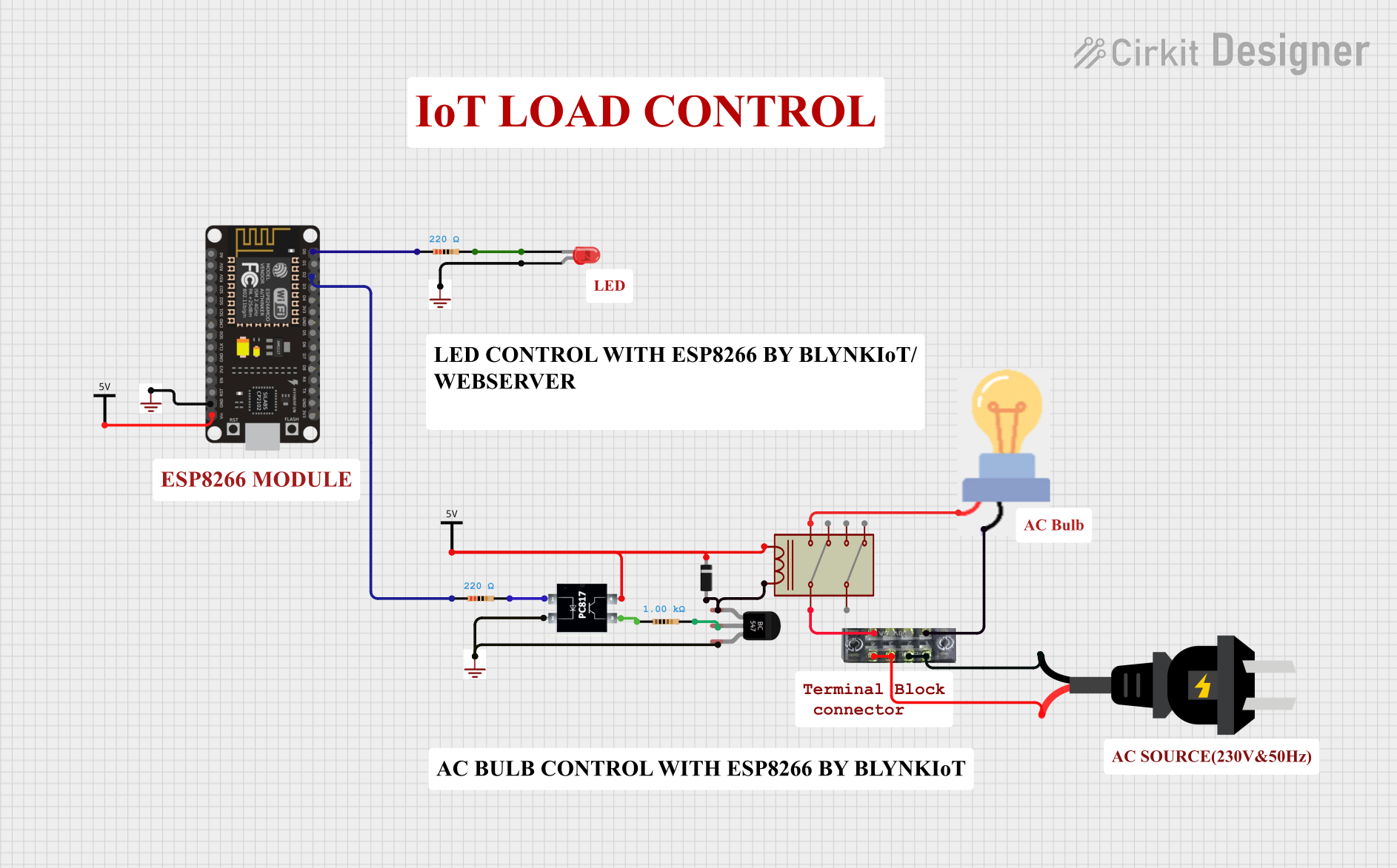
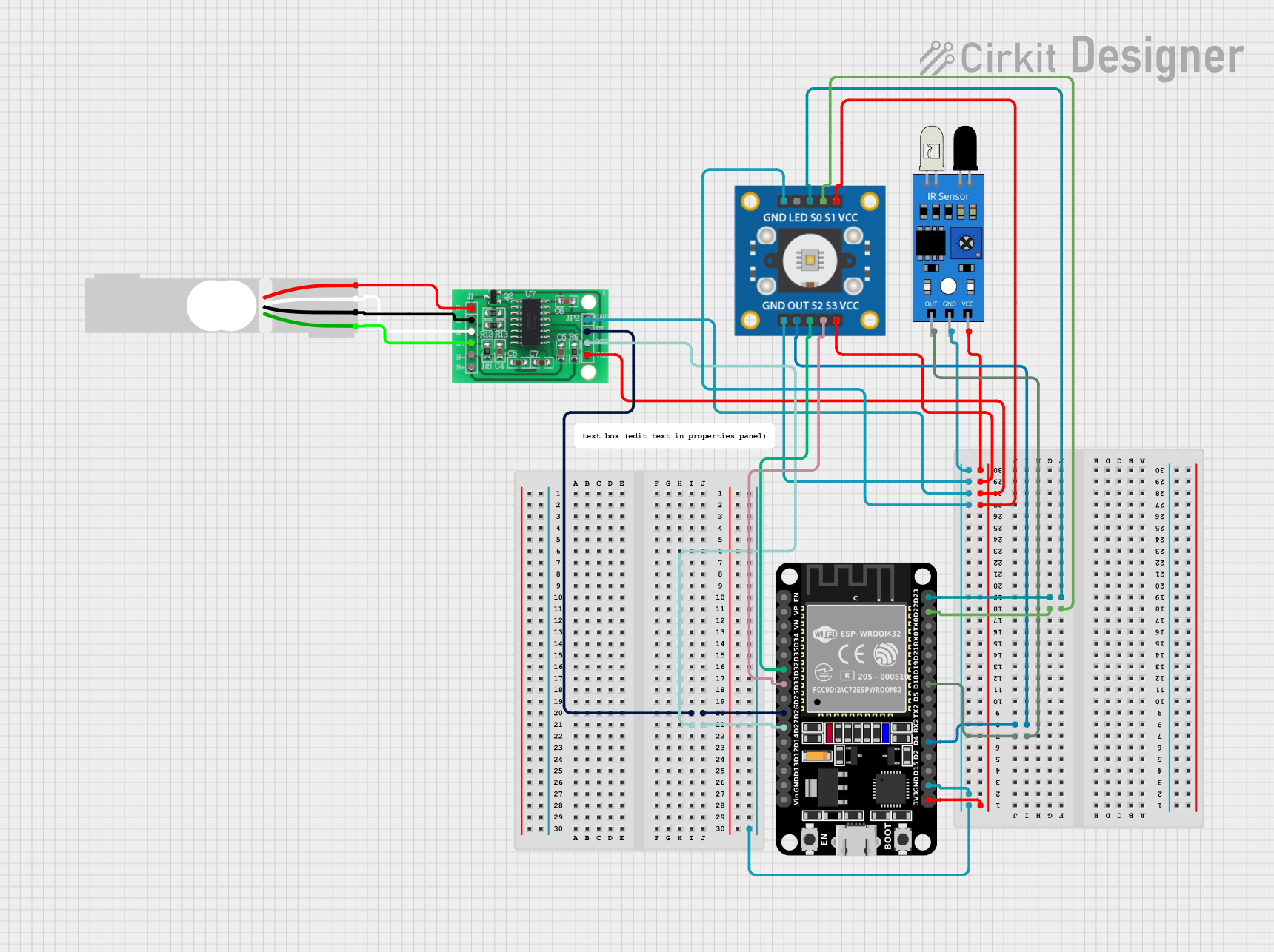
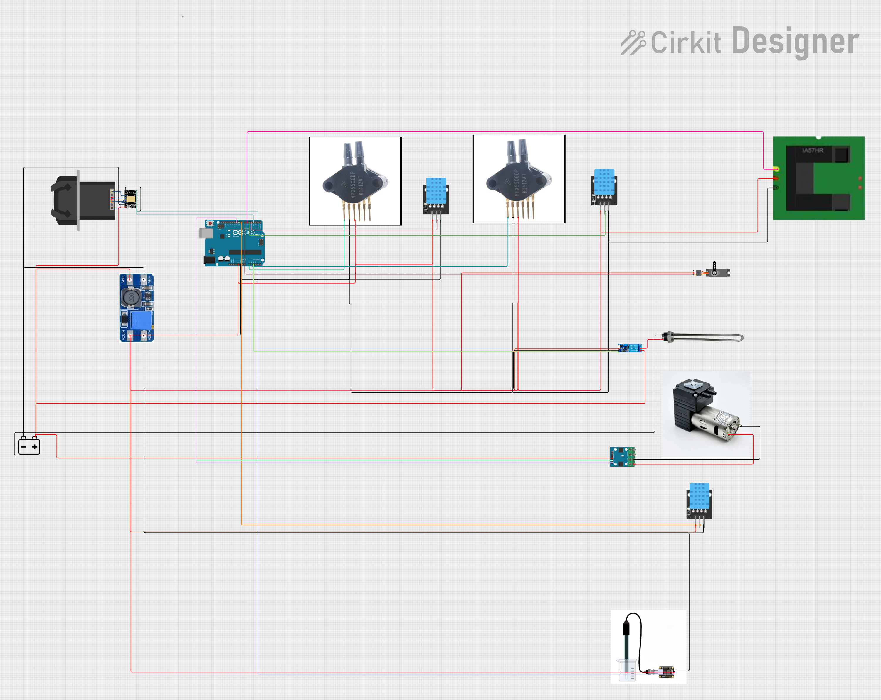

Explore Projects Built with PC817
Common Applications and Use Cases
- Signal isolation in microcontroller circuits
- Interfacing microcontrollers with high voltage systems
- Noise suppression in electronic signals
- Power supply regulation
- Switching power supplies
- Computer peripheral interfaces
Technical Specifications
Key Technical Details
- Forward Current (IF): 50mA (max)
- Reverse Voltage (VR): 6V (max)
- Collector-Emitter Voltage (VCEO): 35V (max)
- Emitter-Collector Voltage (VECO): 6V (max)
- Collector Current (IC): 50mA (max)
- Isolation Voltage (Viso): 5000Vrms (min)
- Current Transfer Ratio (CTR): 50% to 600% at IF=5mA, VCE=5V
- Response Time (tr): 18µs (typ), 100µs (max)
- Operating Temperature: -30°C to +100°C
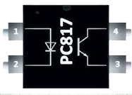
Pin Configuration and Descriptions
| Pin Number | Name | Description |
|---|---|---|
| 1 | Anode (A) | Anode of the infrared LED. |
| 2 | Cathode (K) | Cathode of the infrared LED. |
| 3 | Emitter (E) | Emitter of the phototransistor. |
| 4 | Collector (C) | Collector of the phototransistor. |
Usage Instructions
How to Use the PC817 in a Circuit
- Connect the anode of the LED (pin 1) to the signal you wish to transmit and the cathode (pin 2) to the ground of the transmitting circuit.
- The collector (pin 4) of the phototransistor connects to the positive supply of the receiving circuit, while the emitter (pin 3) connects to the signal receiving point in the receiving circuit.
- A current limiting resistor should be used in series with the LED to prevent excessive current.
- The output side may require a pull-up resistor depending on the application.
Important Considerations and Best Practices
- Ensure the input LED current is within the specified range to prevent damage.
- Avoid exceeding the maximum ratings of voltage and current.
- Provide appropriate heat sinking if operating near maximum ratings.
- Isolation voltage must be maintained to ensure safety and component integrity.
- Check the CTR value for your specific application to ensure proper function.
Example Circuit with Arduino UNO
// Example code for interfacing PC817 with Arduino UNO

const int ledPin = 13; // LED on Arduino board
const int inputPin = 2; // Input pin where PC817 output is connected

void setup() {
  pinMode(ledPin, OUTPUT); // Set the LED pin as output
  pinMode(inputPin, INPUT); // Set the input pin as input
}

void loop() {
  int sensorValue = digitalRead(inputPin); // Read the value from the optocoupler
  if (sensorValue == HIGH) {
    digitalWrite(ledPin, HIGH); // Turn on the LED if signal is received
  } else {
    digitalWrite(ledPin, LOW); // Turn off the LED if signal is not received
  }
}
Troubleshooting and FAQs
Common Issues
- LED not turning on: Check if the input current to the LED is within the specified range and the polarity is correct.
- No signal on the output: Ensure that the phototransistor is correctly connected and that the CTR is sufficient for the application.
- Unexpected behavior: Verify that the isolation voltage is not exceeded and that there are no short circuits.
Solutions and Tips for Troubleshooting
- Double-check the wiring and ensure that all connections are secure.
- Measure the input current to the LED to ensure it is within the safe operating range.
- Use a multimeter to check the continuity and isolation between the input and output sides.
- If the output signal is weak, consider using a transistor or operational amplifier to amplify the signal.
FAQs
Q: Can the PC817 be used to directly drive a relay? A: Yes, but ensure the relay coil current is within the phototransistor's maximum collector current rating.
Q: What is the purpose of the current limiting resistor on the input side? A: The resistor limits the current through the LED to prevent it from exceeding the maximum forward current rating.
Q: How can I increase the isolation between circuits? A: Ensure that the PC817 is mounted with proper spacing and consider using additional isolation techniques such as barriers or optocoupler sockets.
Q: Can the PC817 be used for analog signal transmission? A: Yes, but the linearity and bandwidth may be limited. For precise analog applications, consider using a specialized analog optocoupler.