Cirkit Designer Logo
Cirkit Designer
Your all-in-one circuit design IDE
Home / 
Component Documentation

How to Use IP2312: Examples, Pinouts, and Specs

Image of IP2312
Cirkit Designer LogoDesign with IP2312 in Cirkit Designer

Introduction

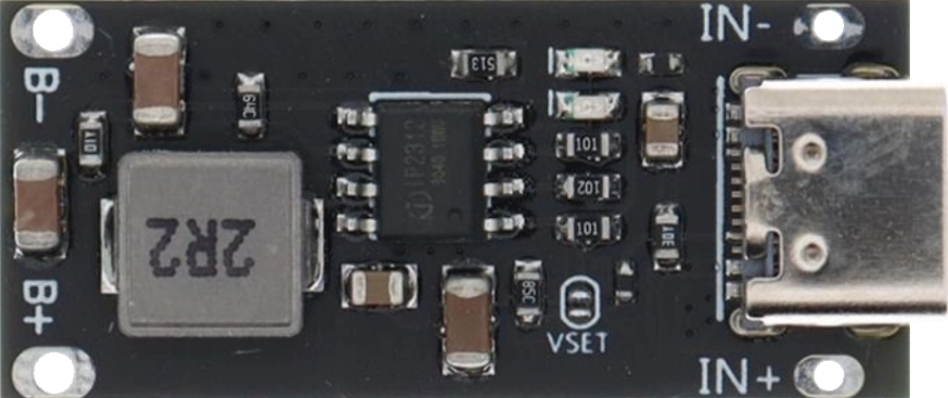
The IP2312, manufactured by Injoinic Technology, is a high-performance power management integrated circuit (PMIC) designed for battery-powered applications. It features a low-dropout (LDO) regulator and multiple output voltage options, making it ideal for efficient power distribution in portable devices. The IP2312 is widely used in applications such as wearable electronics, IoT devices, and portable medical equipment due to its compact size, high efficiency, and reliable performance.

Explore Projects Built with IP2312

Use Cirkit Designer to design, explore, and prototype these projects online. Some projects support real-time simulation. Click "Open Project" to start designing instantly!
Optiplex Micro and PoE Camera Surveillance System with Ethernet Switching
Image of Engine Mounts Wiring: A project utilizing IP2312 in a practical application
This circuit describes a networked system where an Optiplex Micro computer is powered by a PC Power Supply and connected to a PC Screen via HDMI for display output. The computer is networked through an Ethernet Switch, which also connects to two PoE Cameras and a Toyopuc PLC. The Ethernet Switch is powered by a PoE PSU 48V DC, and all AC-powered devices are connected to a common 220V AC source.
Cirkit Designer LogoOpen Project in Cirkit Designer
Cellular-Enabled IoT Device with Real-Time Clock and Power Management
Image of LRCM PHASE 2 BASIC: A project utilizing IP2312 in a practical application
This circuit features a LilyGo-SIM7000G module for cellular communication and GPS functionality, interfaced with an RTC DS3231 for real-time clock capabilities. It includes voltage sensing through two voltage sensor modules, and uses an 8-channel opto-coupler for isolating different parts of the circuit. Power management is handled by a buck converter connected to a DC power source and batteries, with a fuse for protection and a rocker switch for on/off control. Additionally, there's an LED for indication purposes.
Cirkit Designer LogoOpen Project in Cirkit Designer
Sound-Activated LED Lighting with ESP32 and INMP441 Microphone
Image of WS2815 v3: A project utilizing IP2312 in a practical application
This circuit features an ESP32 microcontroller interfacing with an INMP441 microphone module and controlling a WS2815 LED strip, with signal conditioning provided by an SN74AHC14 hex inverter. It includes a 12V power supply with a 5A fuse for protection and uses a ceramic capacitor for voltage regulation.
Cirkit Designer LogoOpen Project in Cirkit Designer
Satellite-Based Timing and Navigation System with SDR and Atomic Clock Synchronization
Image of GPS 시스템 측정 구성도_Confirm: A project utilizing IP2312 in a practical application
This circuit appears to be a complex system involving power supply management, GPS and timing synchronization, and data communication. It includes a SI-TEX G1 Satellite Compass for GPS data, an XHTF1021 Atomic Rubidium Clock for precise timing, and Ettus USRP B200 units for software-defined radio communication. Power is supplied through various SMPS units and distributed via terminal blocks and DC jacks. Data communication is facilitated by Beelink MINI S12 N95 computers, RS232 splitters, and a 1000BASE-T Media Converter for network connectivity. RF Directional Couplers are used to interface antennas with the USRP units, and the entire system is likely contained within cases for protection and organization.
Cirkit Designer LogoOpen Project in Cirkit Designer

Explore Projects Built with IP2312

Use Cirkit Designer to design, explore, and prototype these projects online. Some projects support real-time simulation. Click "Open Project" to start designing instantly!
Image of Engine Mounts Wiring: A project utilizing IP2312 in a practical application
Optiplex Micro and PoE Camera Surveillance System with Ethernet Switching
This circuit describes a networked system where an Optiplex Micro computer is powered by a PC Power Supply and connected to a PC Screen via HDMI for display output. The computer is networked through an Ethernet Switch, which also connects to two PoE Cameras and a Toyopuc PLC. The Ethernet Switch is powered by a PoE PSU 48V DC, and all AC-powered devices are connected to a common 220V AC source.
Cirkit Designer LogoOpen Project in Cirkit Designer
Image of LRCM PHASE 2 BASIC: A project utilizing IP2312 in a practical application
Cellular-Enabled IoT Device with Real-Time Clock and Power Management
This circuit features a LilyGo-SIM7000G module for cellular communication and GPS functionality, interfaced with an RTC DS3231 for real-time clock capabilities. It includes voltage sensing through two voltage sensor modules, and uses an 8-channel opto-coupler for isolating different parts of the circuit. Power management is handled by a buck converter connected to a DC power source and batteries, with a fuse for protection and a rocker switch for on/off control. Additionally, there's an LED for indication purposes.
Cirkit Designer LogoOpen Project in Cirkit Designer
Image of WS2815 v3: A project utilizing IP2312 in a practical application
Sound-Activated LED Lighting with ESP32 and INMP441 Microphone
This circuit features an ESP32 microcontroller interfacing with an INMP441 microphone module and controlling a WS2815 LED strip, with signal conditioning provided by an SN74AHC14 hex inverter. It includes a 12V power supply with a 5A fuse for protection and uses a ceramic capacitor for voltage regulation.
Cirkit Designer LogoOpen Project in Cirkit Designer
Image of GPS 시스템 측정 구성도_Confirm: A project utilizing IP2312 in a practical application
Satellite-Based Timing and Navigation System with SDR and Atomic Clock Synchronization
This circuit appears to be a complex system involving power supply management, GPS and timing synchronization, and data communication. It includes a SI-TEX G1 Satellite Compass for GPS data, an XHTF1021 Atomic Rubidium Clock for precise timing, and Ettus USRP B200 units for software-defined radio communication. Power is supplied through various SMPS units and distributed via terminal blocks and DC jacks. Data communication is facilitated by Beelink MINI S12 N95 computers, RS232 splitters, and a 1000BASE-T Media Converter for network connectivity. RF Directional Couplers are used to interface antennas with the USRP units, and the entire system is likely contained within cases for protection and organization.
Cirkit Designer LogoOpen Project in Cirkit Designer

Common Applications:

  • Wearable devices (e.g., smartwatches, fitness trackers)
  • IoT (Internet of Things) devices
  • Portable medical equipment
  • Battery-powered consumer electronics
  • Wireless communication modules

Technical Specifications

Key Technical Details:

  • Input Voltage Range: 2.5V to 6.5V
  • Output Voltage Options: Configurable (e.g., 1.8V, 3.3V, etc.)
  • Output Current: Up to 1A
  • Low-Dropout Voltage: < 200mV at 500mA load
  • Quiescent Current: < 50µA
  • Efficiency: Up to 95%
  • Operating Temperature Range: -40°C to +85°C
  • Package Type: SOT23-6 or DFN-6 (depending on variant)

Pin Configuration and Descriptions:

The IP2312 is typically available in a 6-pin package. Below is the pinout and description:

SOT23-6 Package Pinout:

Pin Number Pin Name Description
1 VIN Input voltage supply (2.5V to 6.5V).
2 GND Ground connection.
3 EN Enable pin. High to enable the IC, low to disable.
4 FB Feedback pin for output voltage adjustment.
5 VOUT Regulated output voltage.
6 NC No connection (leave floating or connect to GND).

DFN-6 Package Pinout:

Pin Number Pin Name Description
1 VIN Input voltage supply (2.5V to 6.5V).
2 GND Ground connection.
3 EN Enable pin. High to enable the IC, low to disable.
4 FB Feedback pin for output voltage adjustment.
5 VOUT Regulated output voltage.
6 GND (Pad) Exposed thermal pad for heat dissipation.

Usage Instructions

How to Use the IP2312 in a Circuit:

  1. Power Supply: Connect the input voltage (VIN) to a stable DC power source within the range of 2.5V to 6.5V.
  2. Enable Pin: Use a pull-up resistor to enable the IC by driving the EN pin high. To disable the IC, pull the EN pin low.
  3. Output Voltage Configuration:
    • Use a resistor divider network connected to the FB pin to set the desired output voltage.
    • The output voltage (VOUT) can be calculated using the formula:
      [ V_{OUT} = V_{REF} \times \left(1 + \frac{R_1}{R_2}\right) ]
      where ( V_{REF} ) is the internal reference voltage (typically 1.2V).
  4. Output Capacitor: Place a low-ESR capacitor (e.g., 10µF ceramic) at the VOUT pin for stability and noise filtering.
  5. Thermal Management: Ensure proper heat dissipation by connecting the exposed thermal pad (if available) to a large ground plane.

Important Considerations:

  • Input Capacitor: Use a 10µF ceramic capacitor close to the VIN pin to minimize input voltage ripple.
  • Load Regulation: Ensure the load current does not exceed the maximum rated output current (1A).
  • PCB Layout: Keep the feedback trace short and away from noisy signals to maintain output voltage accuracy.

Example: Using IP2312 with Arduino UNO

The IP2312 can be used to power an Arduino UNO by providing a stable 5V output. Below is an example circuit and Arduino code to enable the IC:

Circuit:

  • Connect VIN to a 6V battery.
  • Connect VOUT to the Arduino UNO's 5V pin.
  • Use a 10kΩ pull-up resistor on the EN pin to enable the IC.

Arduino Code:

// Example code to control the EN pin of the IP2312 using Arduino UNO
const int enablePin = 7; // Pin 7 connected to the EN pin of IP2312

void setup() {
  pinMode(enablePin, OUTPUT); // Set enablePin as an output
  digitalWrite(enablePin, HIGH); // Enable the IP2312
}

void loop() {
  // The IP2312 remains enabled, providing power to the Arduino
  delay(1000); // Placeholder for user code
}

Troubleshooting and FAQs

Common Issues and Solutions:

  1. No Output Voltage:

    • Cause: EN pin is not properly configured.
    • Solution: Ensure the EN pin is pulled high to enable the IC.
  2. Output Voltage Instability:

    • Cause: Insufficient output capacitor or poor PCB layout.
    • Solution: Use a low-ESR capacitor (e.g., 10µF ceramic) close to the VOUT pin and minimize feedback trace length.
  3. Excessive Heat:

    • Cause: Overloading or insufficient thermal dissipation.
    • Solution: Ensure the load current does not exceed 1A and connect the thermal pad to a large ground plane.
  4. High Quiescent Current:

    • Cause: Faulty configuration or damaged IC.
    • Solution: Verify the circuit connections and replace the IC if necessary.

FAQs:

  1. Can the IP2312 operate with a 3.7V Li-ion battery?
    Yes, the IP2312 supports input voltages as low as 2.5V, making it compatible with 3.7V Li-ion batteries.

  2. What is the maximum output current of the IP2312?
    The IP2312 can provide up to 1A of output current.

  3. How do I adjust the output voltage?
    Use a resistor divider network connected to the FB pin to set the desired output voltage.

  4. Is the IP2312 suitable for powering microcontrollers?
    Yes, the IP2312 is ideal for powering microcontrollers due to its low dropout voltage and high efficiency.

By following this documentation, users can effectively integrate the IP2312 into their designs for efficient power management.