How to Use batteryERA: Examples, Pinouts, and Specs
Introduction
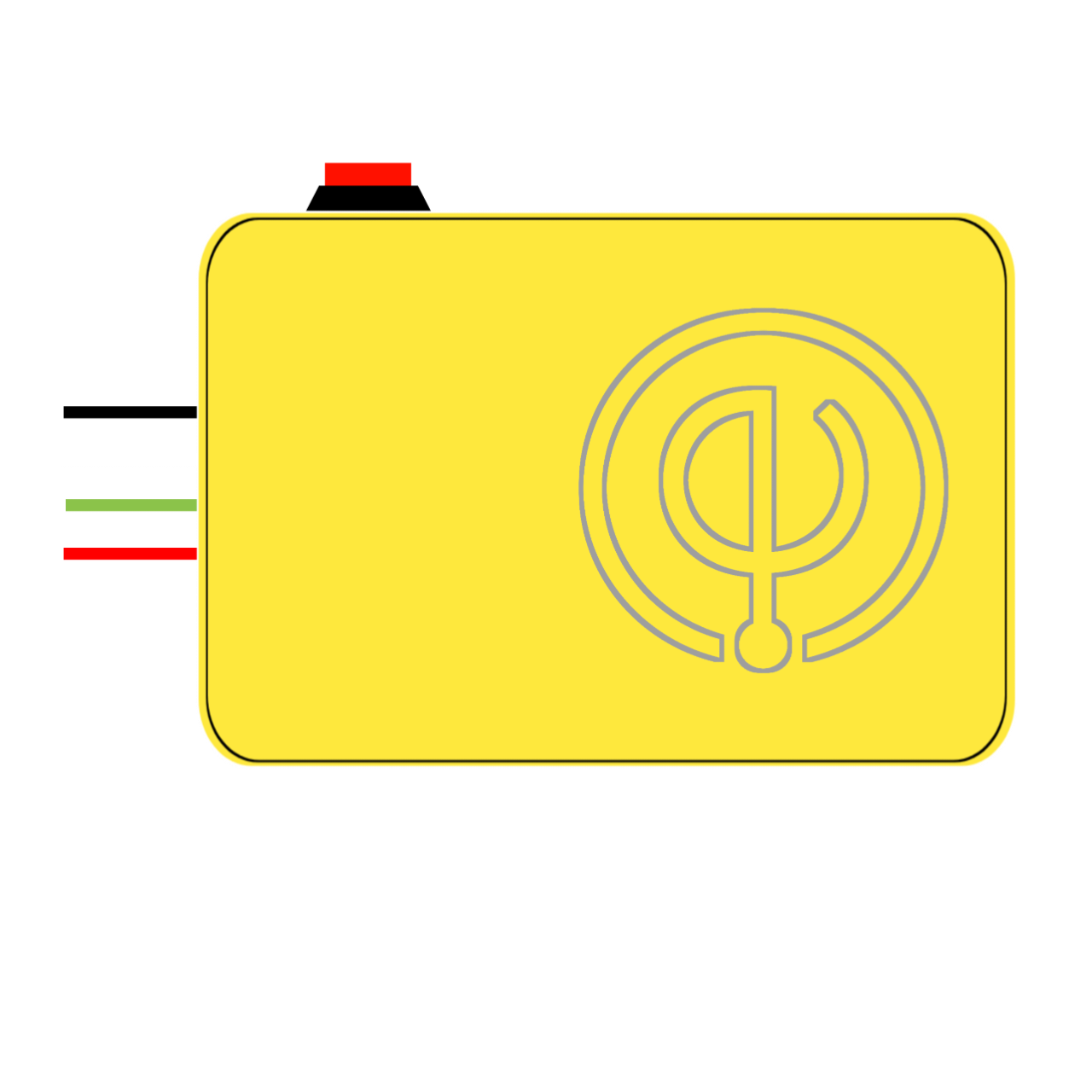
The batteryERA (ETCV.03) is an electrochemical storage device manufactured by ElectroEra, designed to convert chemical energy into electrical energy through redox reactions. This component is essential in a wide range of applications, from portable electronics to backup power systems, and is known for its reliability and efficiency.
Explore Projects Built with batteryERA
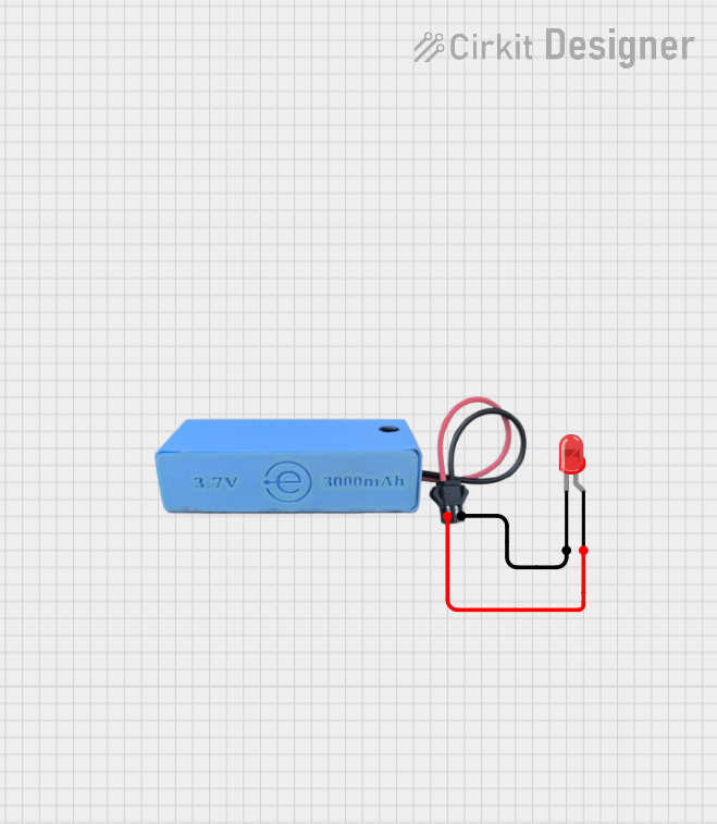

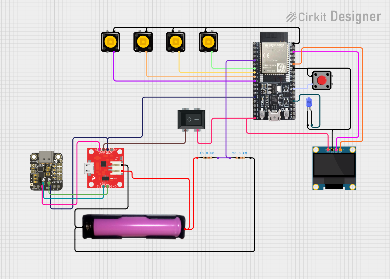
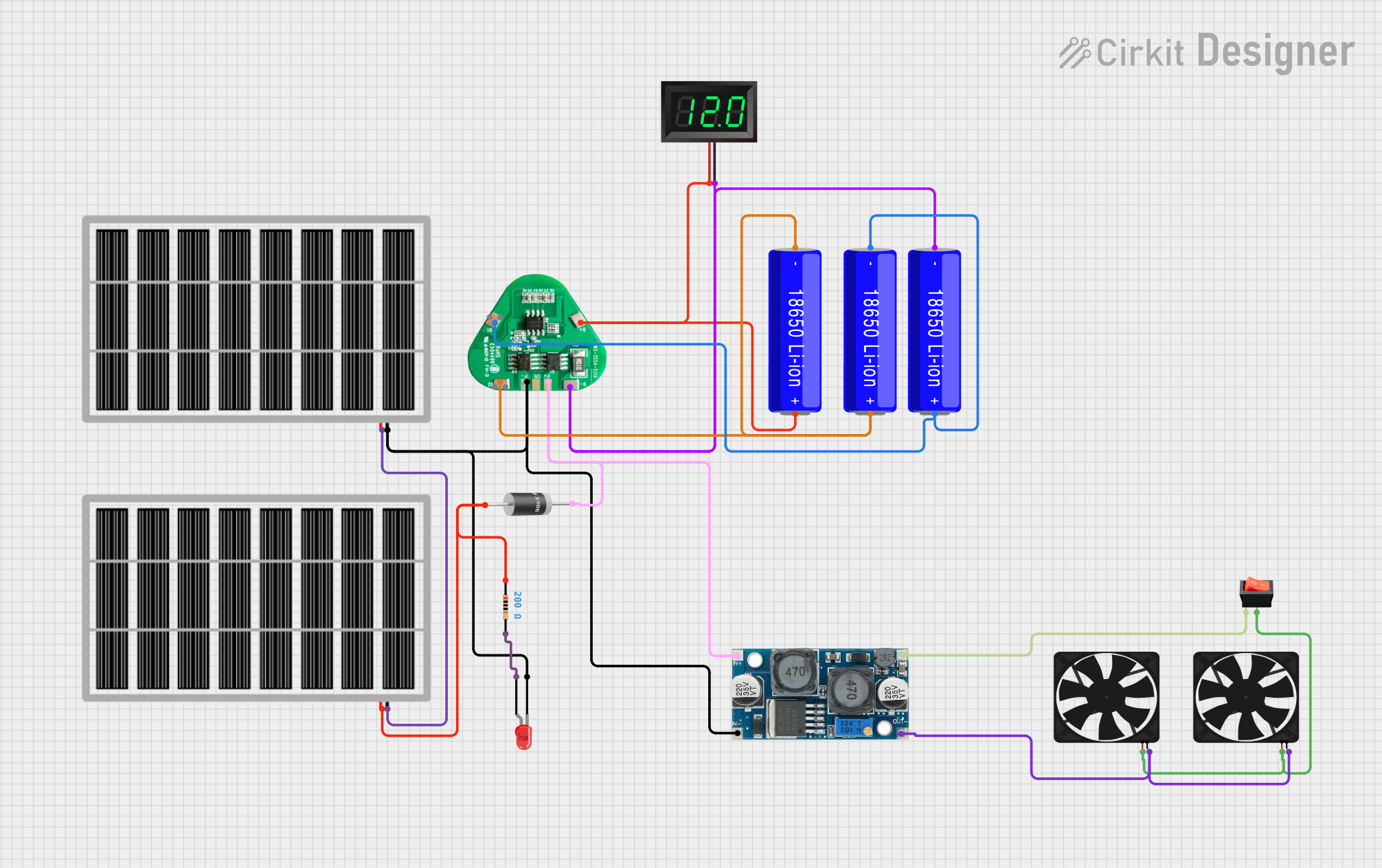
Explore Projects Built with batteryERA
Common Applications and Use Cases:
- Portable electronic devices (e.g., flashlights, handheld gadgets)
- Backup power for emergency systems
- Power supply for small-scale robotics
- Energy storage for renewable energy systems
- DIY projects and educational purposes
Technical Specifications
Key Technical Details:
- Nominal Voltage: 3.7V
- Capacity: 2200mAh
- Maximum Charging Voltage: 4.2V
- Maximum Discharge Current: 2A
- Chemistry: Lithium-Ion
- Cycle Life: >500 cycles
- Operating Temperature Range: -20°C to 60°C
Pin Configuration and Descriptions:
| Pin Number | Description | Notes |
|---|---|---|
| 1 | Positive Terminal | Connect to the positive load/circuit |
| 2 | Negative Terminal | Connect to the negative load/circuit |
Usage Instructions
How to Use the batteryERA in a Circuit:
- Initial Inspection: Before using the batteryERA, inspect it for any physical damage or deformities.
- Charging: Use a compatible charger with a maximum voltage of 4.2V. Do not overcharge.
- Discharging: Do not exceed the maximum discharge current of 2A to prevent overheating.
- Connection: Connect the positive terminal to the positive input of your load and the negative terminal to the negative input.
- Monitoring: Always monitor the battery temperature and voltage during charging and discharging.
Important Considerations and Best Practices:
- Avoid exposing the batteryERA to extreme temperatures or moisture.
- Do not puncture, crush, or disassemble the battery.
- Use a battery management system (BMS) for charging and discharging to ensure safety.
- Store the battery in a cool, dry place when not in use.
- Recycle the battery properly at the end of its life cycle.
Troubleshooting and FAQs
Common Issues and Solutions:
- Battery not charging: Ensure the charger is functioning and the connections are secure. Check for any damage to the battery.
- Reduced capacity: This may indicate the battery is nearing the end of its life cycle. Consider replacing it if performance is significantly degraded.
- Overheating during use: Reduce the load or discontinue use to allow the battery to cool down.
FAQs:
Q: Can the batteryERA be used in series or parallel configurations?
- A: Yes, but it is crucial to match batteries of the same age and capacity to prevent imbalances.
Q: What should I do if the batteryERA gets wet?
- A: Disconnect it from any circuit and allow it to dry completely. Check for any signs of damage before reuse.
Q: Is it necessary to fully discharge the battery before recharging?
- A: No, lithium-ion batteries do not have a memory effect and can be charged at any state of discharge.
Example Arduino UNO Connection
// Example code to monitor battery voltage using Arduino UNO

const int batteryPin = A0; // Connect battery positive terminal to A0

void setup() {
  Serial.begin(9600);
}

void loop() {
  int sensorValue = analogRead(batteryPin);
  float voltage = sensorValue * (5.0 / 1023.0); // Convert the reading to voltage
  Serial.print("Battery Voltage: ");
  Serial.println(voltage);
  delay(1000); // Wait for a second before reading again
}
Note: This example assumes a direct connection between the battery and the Arduino analog pin. In practice, a voltage divider or level shifter may be required to match the Arduino's input voltage range.
For further assistance or inquiries regarding the batteryERA (ETCV.03), please contact ElectroEra's customer support.