How to Use SparkFun RedBoard Artemis: Examples, Pinouts, and Specs
Introduction
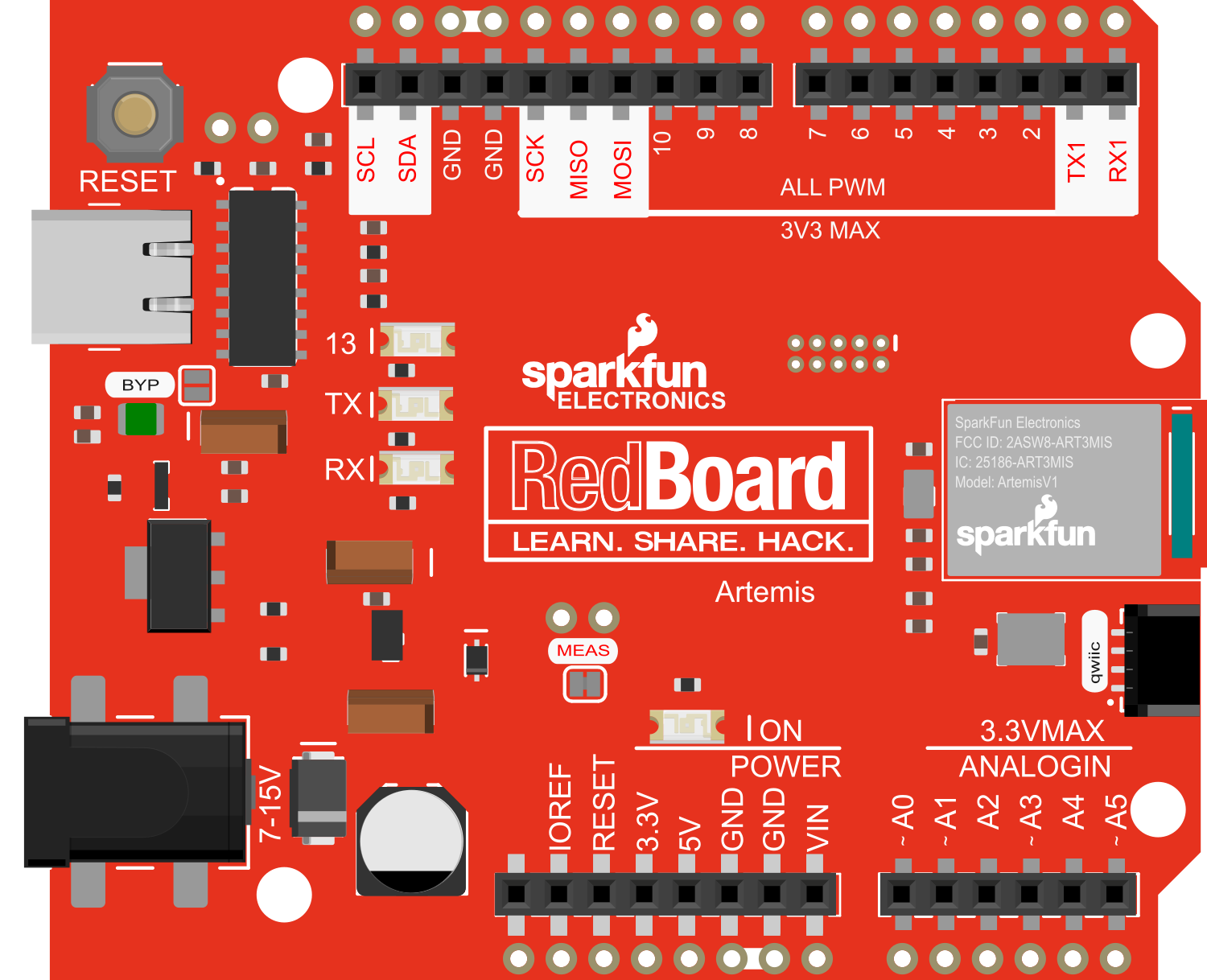
The SparkFun RedBoard Artemis is an all-in-one development board that integrates the powerful Artemis module, which is based on the Ambiq Apollo3 microcontroller. This board is designed to be a bridge between hobbyist and professional environments, offering the ease-of-use of the Arduino ecosystem with the advanced features of the Artemis module. The Cortex-M4F processor core provides ample computational power, and the board's rich set of peripherals makes it suitable for a wide range of applications, from simple LED blink projects to complex machine learning tasks.
Explore Projects Built with SparkFun RedBoard Artemis
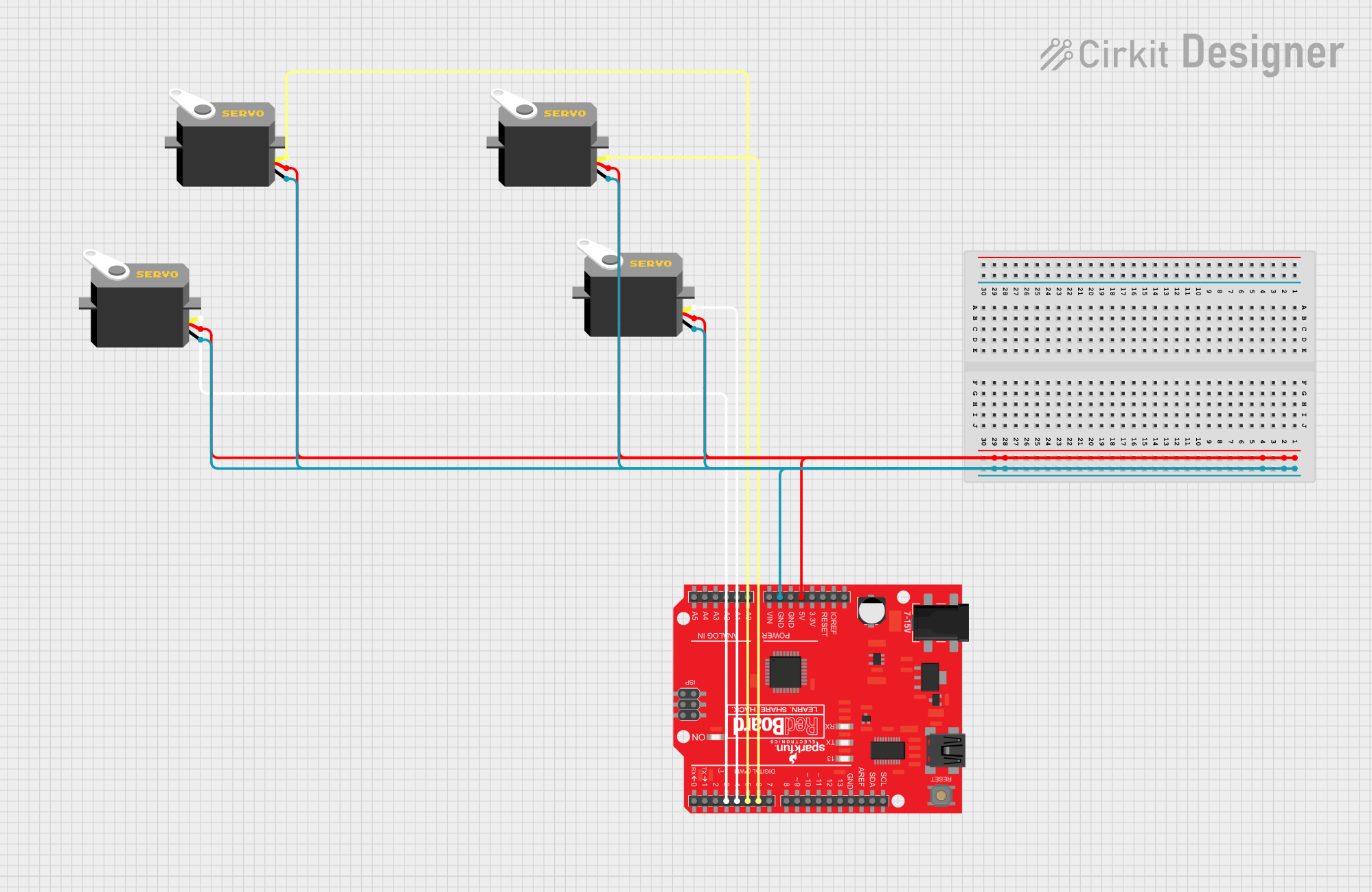
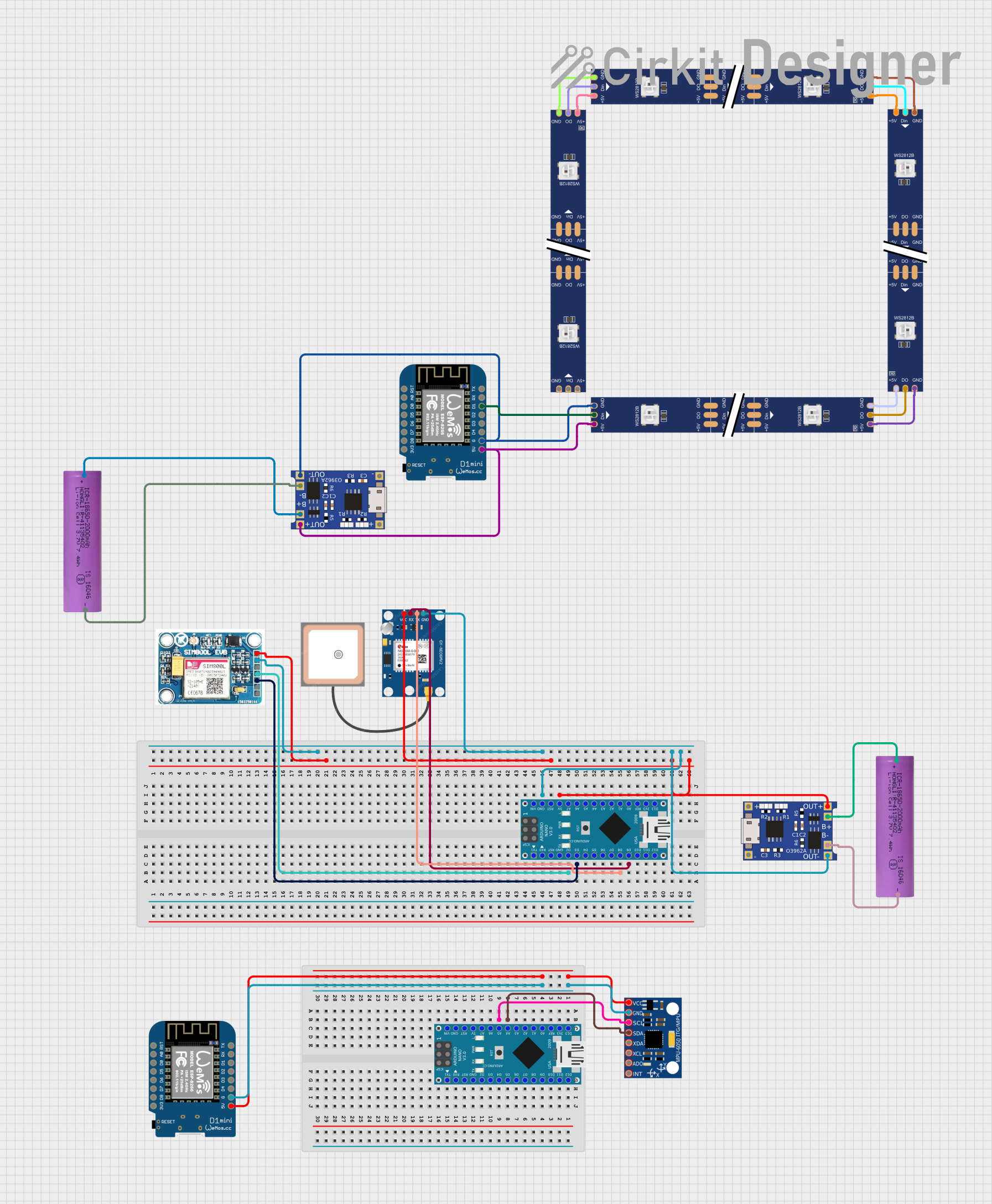
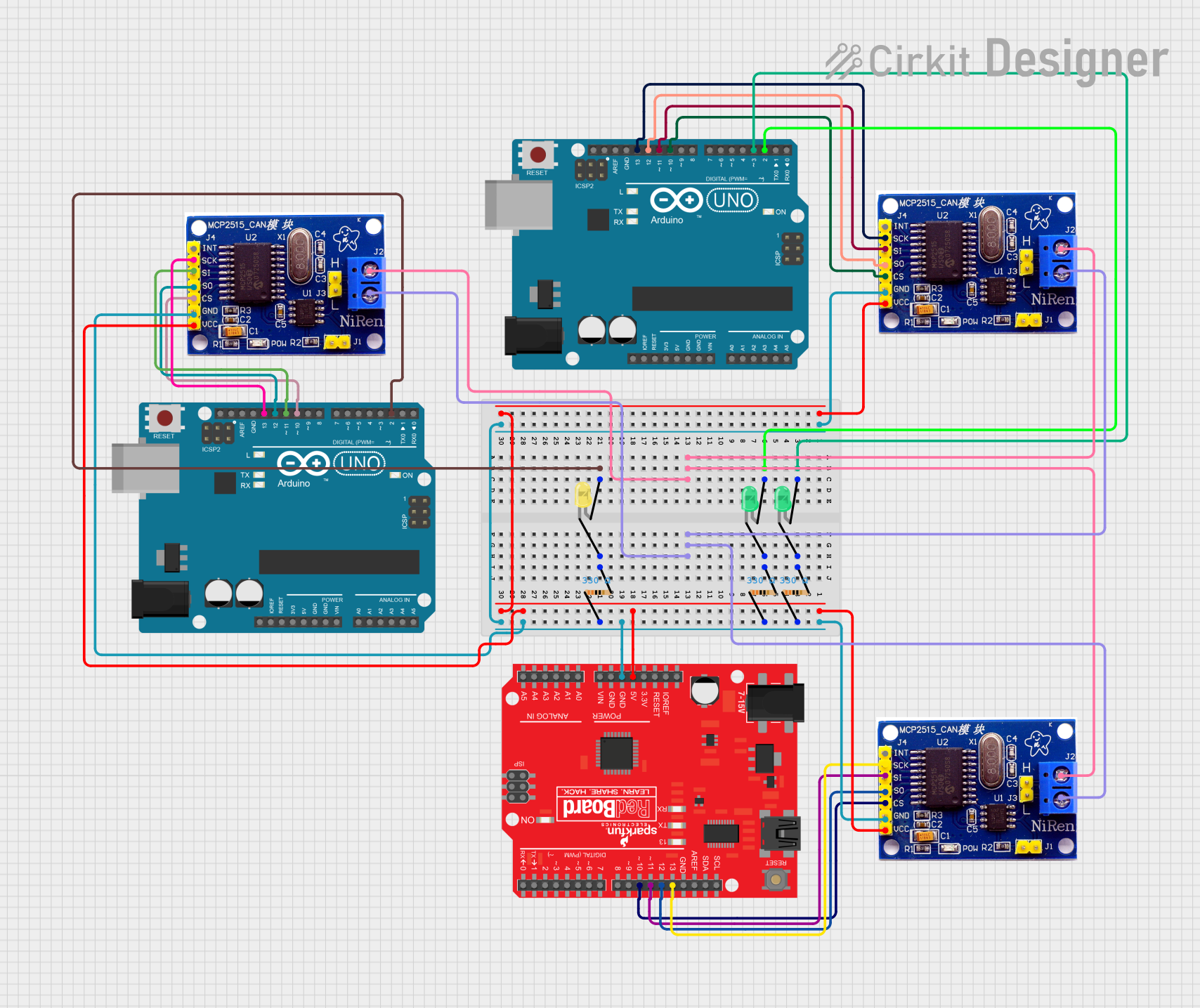

Explore Projects Built with SparkFun RedBoard Artemis
Common Applications and Use Cases
- Wearable devices
- Low-power sensor networks
- Machine learning applications
- Educational purposes and prototyping
- IoT and smart home devices
Technical Specifications
Key Technical Details
- Microcontroller: Ambiq Apollo3 ARM Cortex-M4F with FPU
- Operating Voltage: 3.3V
- Input Voltage: 5V via USB or 4-6V via the VIN pin
- I/O Pin Voltage: 3.3V, all are digital capable, some are analog capable
- Clock Speed: 48MHz (up to 96MHz burst mode)
- Flash Memory: 1MB
- SRAM: 384KB
- Bluetooth: BLE 5.0
Pin Configuration and Descriptions
| Pin Number | Function | Description |
|---|---|---|
| 1 | GND | Ground |
| 2 | 3.3V | 3.3V power supply |
| 3 | VIN | Voltage input for board power (4-6V) |
| 4 | RESET | Reset pin (active low) |
| 5-28 | Digital Pins | Digital I/O, some can be used as PWM or analog |
| 29-34 | Analog Pins | Analog input pins |
| 35-38 | I2C/SPI | Communication pins for I2C and SPI |
| 39-40 | RX/TX | UART communication pins |
Usage Instructions
How to Use the Component in a Circuit
- Powering the Board: Connect the board to your computer via a USB cable or supply power through the VIN pin.
- Connecting I/O: Utilize the digital and analog pins to interface with sensors, actuators, and other components.
- Programming: Use the Arduino IDE or other supported development environments to write and upload code to the board.
Important Considerations and Best Practices
- Always ensure that the power supply is within the specified range to prevent damage.
- When connecting external components, make sure they are compatible with the 3.3V logic level.
- Avoid drawing more than 10mA from any I/O pin.
- Use the onboard LED (usually connected to pin 13) for simple debugging.
- For Bluetooth applications, ensure compliance with BLE protocols and standards.
Troubleshooting and FAQs
Common Issues Users Might Face
- Board not recognized by the computer: Check the USB cable and drivers.
- Failure to upload code: Ensure the correct board and port are selected in the IDE.
- Unexpected behavior in circuits: Verify connections and power supply voltages.
Solutions and Tips for Troubleshooting
- Use a different USB port or cable if the board is not recognized.
- Double-check the board selection in your development environment.
- Ensure that all external components are correctly connected and powered.
- Consult the board's schematic and datasheet for detailed information.
FAQs
Q: Can I use the Arduino IDE with the RedBoard Artemis? A: Yes, the RedBoard Artemis is compatible with the Arduino IDE.
Q: What is the maximum voltage that can be applied to the I/O pins? A: The maximum voltage for the I/O pins is 3.3V.
Q: Does the RedBoard Artemis support battery operation? A: Yes, it can be powered by a battery connected to the VIN pin.
Q: How do I enable Bluetooth functionality? A: Bluetooth can be enabled through the appropriate libraries and code within the Arduino IDE or other development environments.
Example Code for Arduino UNO
Below is a simple example of how to blink the onboard LED using the Arduino IDE:
// Define the LED pin
const int ledPin = 13;

// The setup function runs once when you press reset or power the board
void setup() {
  // Initialize the LED pin as an output
  pinMode(ledPin, OUTPUT);
}

// The loop function runs over and over again forever
void loop() {
  digitalWrite(ledPin, HIGH);   // Turn the LED on
  delay(1000);                  // Wait for a second
  digitalWrite(ledPin, LOW);    // Turn the LED off
  delay(1000);                  // Wait for a second
}
Remember to select the appropriate board from the Tools menu in the Arduino IDE before uploading the code.