Cirkit Designer Logo
Cirkit Designer
Your all-in-one circuit design IDE
Home / 
Component Documentation

How to Use esp8266 nodemcu : Examples, Pinouts, and Specs

Image of esp8266 nodemcu
Cirkit Designer LogoDesign with esp8266 nodemcu in Cirkit Designer

Introduction

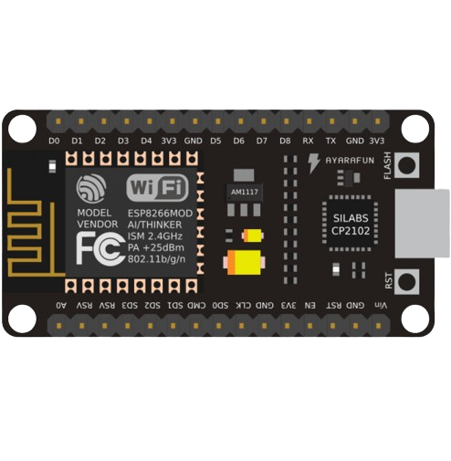
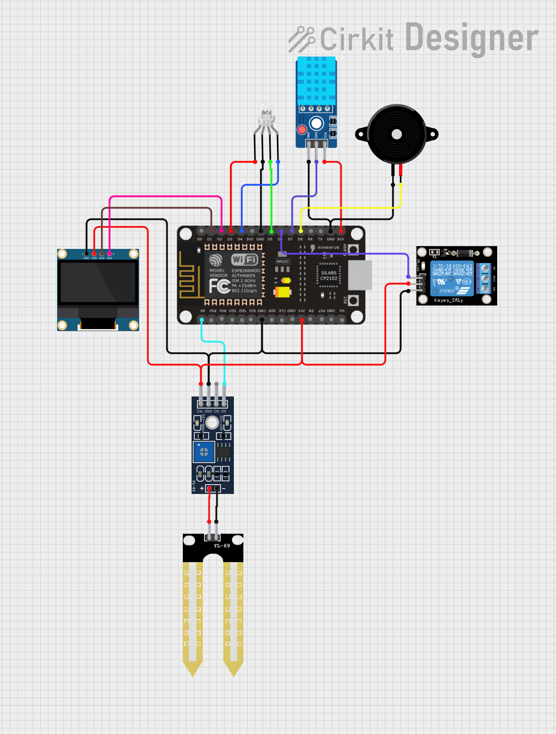
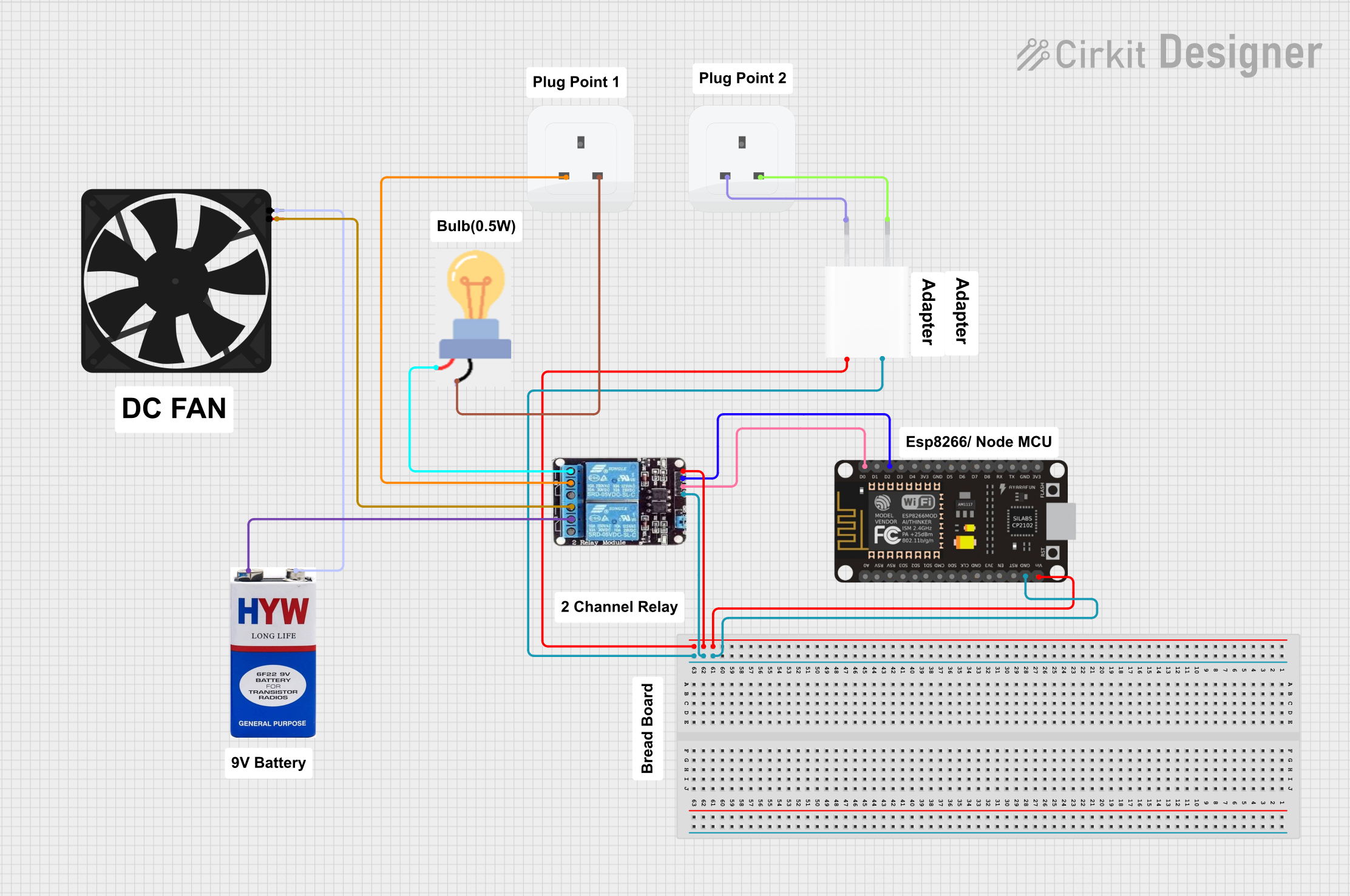
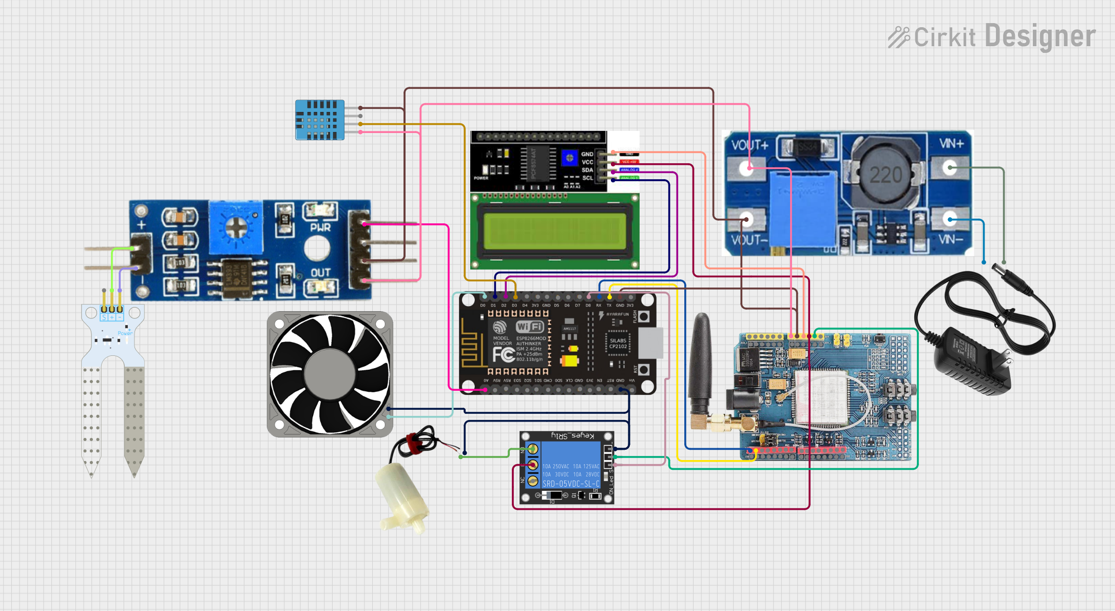
The ESP8266 NodeMCU is an open-source IoT platform that incorporates the ESP8266 Wi-Fi module. It is designed for the Internet of Things (IoT) and is programmable via the Arduino Integrated Development Environment (IDE). The NodeMCU board is favored for its Wi-Fi capability, ease of use, and the extensive community support available. Common applications include smart home devices, wireless sensors, and internet-connected automation.

Explore Projects Built with esp8266 nodemcu

Use Cirkit Designer to design, explore, and prototype these projects online. Some projects support real-time simulation. Click "Open Project" to start designing instantly!
ESP8266 NodeMCU Controlled Environmental Monitoring System with OLED Display and Relay Switching
Image of soil moisture: A project utilizing esp8266 nodemcu  in a practical application
This circuit features an ESP8266 NodeMCU microcontroller connected to various peripherals. It includes a DHT11 sensor for temperature and humidity readings, a YL-83 module with YL-69 probe for soil moisture detection, a 0.96" OLED display for data output, a common cathode RGB LED for status indication, a piezo speaker for audio alerts, and a KY-019 relay module for controlling external loads. The NodeMCU facilitates data acquisition from sensors, drives the display and LED, and can trigger the relay and speaker based on sensor inputs or programmed conditions.
Cirkit Designer LogoOpen Project in Cirkit Designer
ESP8266 and SIM800L Based GPS Tracker with I2C LCD Display and Battery Power
Image of Little Innovator Competition: A project utilizing esp8266 nodemcu  in a practical application
This circuit integrates an ESP8266 NodeMCU microcontroller with a SIM800L GSM module, a GPS NEO 6M module, and a 16x2 I2C LCD display for communication and location tracking. It also includes a pushbutton for user input, a piezo buzzer for audio alerts, and is powered by a 2x 18650 battery pack through an LM2596 step-down module.
Cirkit Designer LogoOpen Project in Cirkit Designer
Wi-Fi Controlled Smart Home Automation with ESP8266 and Relay Module
Image of Vox Domus: A project utilizing esp8266 nodemcu  in a practical application
This circuit is a smart home automation system using an ESP8266 NodeMCU to control a 2-channel relay module, which in turn controls a fan and a bulb. The system is powered by a 5V adapter and a 9V battery, and it uses WiFi to connect to the SinricPro platform for remote control via a mobile app.
Cirkit Designer LogoOpen Project in Cirkit Designer
ESP8266 NodeMCU-Based Smart Irrigation System with GSM Reporting and Environmental Monitoring
Image of Ismail_Fab Project: A project utilizing esp8266 nodemcu  in a practical application
This circuit features an ESP8266 NodeMCU microcontroller connected to various sensors and modules for environmental monitoring and control. It interfaces with a DHT11 temperature and humidity sensor, a soil moisture sensor, and a GSM SIM900 module for communication. Additionally, the circuit can control a 12V fan and a 5V mini water pump via a relay, and it includes a step-up voltage regulator to supply the necessary voltages, as well as an LCD display for user interface.
Cirkit Designer LogoOpen Project in Cirkit Designer

Explore Projects Built with esp8266 nodemcu

Use Cirkit Designer to design, explore, and prototype these projects online. Some projects support real-time simulation. Click "Open Project" to start designing instantly!
Image of soil moisture: A project utilizing esp8266 nodemcu  in a practical application
ESP8266 NodeMCU Controlled Environmental Monitoring System with OLED Display and Relay Switching
This circuit features an ESP8266 NodeMCU microcontroller connected to various peripherals. It includes a DHT11 sensor for temperature and humidity readings, a YL-83 module with YL-69 probe for soil moisture detection, a 0.96" OLED display for data output, a common cathode RGB LED for status indication, a piezo speaker for audio alerts, and a KY-019 relay module for controlling external loads. The NodeMCU facilitates data acquisition from sensors, drives the display and LED, and can trigger the relay and speaker based on sensor inputs or programmed conditions.
Cirkit Designer LogoOpen Project in Cirkit Designer
Image of Little Innovator Competition: A project utilizing esp8266 nodemcu  in a practical application
ESP8266 and SIM800L Based GPS Tracker with I2C LCD Display and Battery Power
This circuit integrates an ESP8266 NodeMCU microcontroller with a SIM800L GSM module, a GPS NEO 6M module, and a 16x2 I2C LCD display for communication and location tracking. It also includes a pushbutton for user input, a piezo buzzer for audio alerts, and is powered by a 2x 18650 battery pack through an LM2596 step-down module.
Cirkit Designer LogoOpen Project in Cirkit Designer
Image of Vox Domus: A project utilizing esp8266 nodemcu  in a practical application
Wi-Fi Controlled Smart Home Automation with ESP8266 and Relay Module
This circuit is a smart home automation system using an ESP8266 NodeMCU to control a 2-channel relay module, which in turn controls a fan and a bulb. The system is powered by a 5V adapter and a 9V battery, and it uses WiFi to connect to the SinricPro platform for remote control via a mobile app.
Cirkit Designer LogoOpen Project in Cirkit Designer
Image of Ismail_Fab Project: A project utilizing esp8266 nodemcu  in a practical application
ESP8266 NodeMCU-Based Smart Irrigation System with GSM Reporting and Environmental Monitoring
This circuit features an ESP8266 NodeMCU microcontroller connected to various sensors and modules for environmental monitoring and control. It interfaces with a DHT11 temperature and humidity sensor, a soil moisture sensor, and a GSM SIM900 module for communication. Additionally, the circuit can control a 12V fan and a 5V mini water pump via a relay, and it includes a step-up voltage regulator to supply the necessary voltages, as well as an LCD display for user interface.
Cirkit Designer LogoOpen Project in Cirkit Designer

Technical Specifications

Key Technical Details

  • Microcontroller: ESP8266
  • Operating Voltage: 3.3V
  • Input Voltage: 7-12V (via Vin pin), 5V (via micro USB)
  • Digital I/O Pins: 16
  • Analog Input Pins: 1 (A0)
  • Flash Memory: 4MB
  • Clock Speed: 80MHz (can be overclocked to 160MHz)
  • Wi-Fi: Built-in 802.11 b/g/n
  • I2C, SPI, UART: Available

Pin Configuration and Descriptions

Pin Function Description
D0 - D8 GPIO, PWM, I2C, SPI General-purpose input/output pins with various functions
A0 Analog Input Single analog input, max input of 3.3V
RX UART Receive Serial communication (receiving)
TX UART Transmit Serial communication (transmitting)
RST Reset Resets the module
VIN Voltage Input External power supply (7-12V)
3V3 3.3V Power Power output (3.3V)
GND Ground Common ground for power and logic

Usage Instructions

Integrating with a Circuit

  1. Powering the NodeMCU: The NodeMCU can be powered via the micro USB port or through the VIN pin with a 7-12V power supply.
  2. Programming: Use the micro USB port to connect the NodeMCU to a computer for programming with the Arduino IDE.
  3. Digital I/O: Connect sensors, actuators, or other modules to the GPIO pins, ensuring they are 3.3V compatible.
  4. Analog Input: The A0 pin can be used for analog sensors, with a maximum input voltage of 3.3V.

Important Considerations and Best Practices

  • Voltage Levels: The NodeMCU operates at 3.3V logic levels. Ensure that any connected components are compatible to avoid damage.
  • Wi-Fi Connectivity: When using Wi-Fi, place the NodeMCU in a location with minimal interference and a strong signal.
  • Firmware Updates: Keep the NodeMCU firmware up to date for the best performance and security.
  • Static Electricity: Handle the NodeMCU with care to avoid damage from static discharge.

Example Code for Arduino UNO

#include <ESP8266WiFi.h>

// Replace with your network credentials
const char* ssid = "your_SSID";
const char* password = "your_PASSWORD";

void setup() {
  Serial.begin(115200); // Start serial communication at 115200 baud
  WiFi.begin(ssid, password); // Connect to Wi-Fi

  while (WiFi.status() != WL_CONNECTED) {
    delay(500);
    Serial.print(".");
  }

  Serial.println("");
  Serial.println("WiFi connected.");
  Serial.println("IP address: ");
  Serial.println(WiFi.localIP()); // Print the local IP address
}

void loop() {
  // Your code here
}

Troubleshooting and FAQs

Common Issues

  • NodeMCU not connecting to Wi-Fi: Ensure the SSID and password are correct. Check the signal strength and router settings.
  • NodeMCU not recognized by computer: Check the USB cable and drivers. Try a different USB port or cable.
  • GPIO pin not working: Verify the pin number in your code. Check for shorts or damage to the board.

Solutions and Tips for Troubleshooting

  • Wi-Fi Connectivity: If you have trouble connecting to Wi-Fi, try moving closer to the router or eliminating sources of interference.
  • Driver Installation: Ensure that the correct USB drivers for the NodeMCU are installed on your computer.
  • Code Debugging: Use Serial.print() statements to debug and track the flow of your program.

FAQs

Q: Can I use 5V components with the NodeMCU? A: No, the NodeMCU operates at 3.3V. Use a logic level converter for 5V components.

Q: How do I reset the NodeMCU? A: Briefly press the RST button on the board to reset it.

Q: Can I use the Arduino IDE for programming the NodeMCU? A: Yes, the NodeMCU is compatible with the Arduino IDE. Make sure to install the ESP8266 board package.

Q: How many digital pins can be used for PWM? A: All digital pins on the NodeMCU can be used for PWM.

This documentation provides an overview of the ESP8266 NodeMCU, its technical specifications, usage instructions, example code, and troubleshooting tips. For further assistance, consult the NodeMCU community forums and resources.