Cirkit Designer Logo
Cirkit Designer
Your all-in-one circuit design IDE
Home / 
Component Documentation

How to Use RYLR998: Examples, Pinouts, and Specs

Image of RYLR998
Cirkit Designer LogoDesign with RYLR998 in Cirkit Designer

Introduction

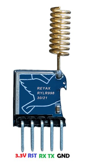
The RYLR998 is a high-performance LoRa wireless transceiver module designed by Rayax. It operates in the global ISM frequency bands, providing long-range communication capabilities with low power consumption. This makes it an ideal choice for Internet of Things (IoT) applications, remote sensor networks, home automation, and other applications where wireless communication over long distances is required.

Explore Projects Built with RYLR998

Use Cirkit Designer to design, explore, and prototype these projects online. Some projects support real-time simulation. Click "Open Project" to start designing instantly!
Cellular-Enabled IoT Device with Real-Time Clock and Power Management
Image of LRCM PHASE 2 BASIC: A project utilizing RYLR998 in a practical application
This circuit features a LilyGo-SIM7000G module for cellular communication and GPS functionality, interfaced with an RTC DS3231 for real-time clock capabilities. It includes voltage sensing through two voltage sensor modules, and uses an 8-channel opto-coupler for isolating different parts of the circuit. Power management is handled by a buck converter connected to a DC power source and batteries, with a fuse for protection and a rocker switch for on/off control. Additionally, there's an LED for indication purposes.
Cirkit Designer LogoOpen Project in Cirkit Designer
Battery-Powered Emergency Alert System with NUCLEO-F072RB, SIM800L, and GPS NEO 6M
Image of women safety: A project utilizing RYLR998 in a practical application
This circuit is an emergency alert system that uses a NUCLEO-F072RB microcontroller to send SMS alerts and make calls via a SIM800L GSM module, while obtaining location data from a GPS NEO 6M module. The system is powered by a Li-ion battery and includes a TP4056 module for battery charging and protection, with a rocker switch to control power to the microcontroller.
Cirkit Designer LogoOpen Project in Cirkit Designer
Dual-Mode LoRa and GSM Communication Device with ESP32
Image of modul gateway: A project utilizing RYLR998 in a practical application
This circuit features an ESP32 Devkit V1 microcontroller interfaced with an RFM95 LoRa transceiver module for long-range communication and a SIM800L GSM module for cellular connectivity. Two LM2596 step-down modules are used to regulate the 12V battery voltage down to 3.3V required by the ESP32, RFM95, and SIM800L. The ESP32 facilitates data exchange between the RFM95 and SIM800L, enabling the system to send/receive data over both LoRa and GSM networks.
Cirkit Designer LogoOpen Project in Cirkit Designer
Battery-Powered Line Following Robot with IR Sensors and Cytron URC10 Motor Controller
Image of URC10 SUMO AUTO: A project utilizing RYLR998 in a practical application
This circuit is a robotic control system that uses multiple IR sensors for line detection and obstacle avoidance, powered by a 3S LiPo battery. The Cytron URC10 motor driver, controlled by a microcontroller, drives two GM25 DC motors based on input from the sensors and a rocker switch, with a 7-segment panel voltmeter displaying the battery voltage.
Cirkit Designer LogoOpen Project in Cirkit Designer

Explore Projects Built with RYLR998

Use Cirkit Designer to design, explore, and prototype these projects online. Some projects support real-time simulation. Click "Open Project" to start designing instantly!
Image of LRCM PHASE 2 BASIC: A project utilizing RYLR998 in a practical application
Cellular-Enabled IoT Device with Real-Time Clock and Power Management
This circuit features a LilyGo-SIM7000G module for cellular communication and GPS functionality, interfaced with an RTC DS3231 for real-time clock capabilities. It includes voltage sensing through two voltage sensor modules, and uses an 8-channel opto-coupler for isolating different parts of the circuit. Power management is handled by a buck converter connected to a DC power source and batteries, with a fuse for protection and a rocker switch for on/off control. Additionally, there's an LED for indication purposes.
Cirkit Designer LogoOpen Project in Cirkit Designer
Image of women safety: A project utilizing RYLR998 in a practical application
Battery-Powered Emergency Alert System with NUCLEO-F072RB, SIM800L, and GPS NEO 6M
This circuit is an emergency alert system that uses a NUCLEO-F072RB microcontroller to send SMS alerts and make calls via a SIM800L GSM module, while obtaining location data from a GPS NEO 6M module. The system is powered by a Li-ion battery and includes a TP4056 module for battery charging and protection, with a rocker switch to control power to the microcontroller.
Cirkit Designer LogoOpen Project in Cirkit Designer
Image of modul gateway: A project utilizing RYLR998 in a practical application
Dual-Mode LoRa and GSM Communication Device with ESP32
This circuit features an ESP32 Devkit V1 microcontroller interfaced with an RFM95 LoRa transceiver module for long-range communication and a SIM800L GSM module for cellular connectivity. Two LM2596 step-down modules are used to regulate the 12V battery voltage down to 3.3V required by the ESP32, RFM95, and SIM800L. The ESP32 facilitates data exchange between the RFM95 and SIM800L, enabling the system to send/receive data over both LoRa and GSM networks.
Cirkit Designer LogoOpen Project in Cirkit Designer
Image of URC10 SUMO AUTO: A project utilizing RYLR998 in a practical application
Battery-Powered Line Following Robot with IR Sensors and Cytron URC10 Motor Controller
This circuit is a robotic control system that uses multiple IR sensors for line detection and obstacle avoidance, powered by a 3S LiPo battery. The Cytron URC10 motor driver, controlled by a microcontroller, drives two GM25 DC motors based on input from the sensors and a rocker switch, with a 7-segment panel voltmeter displaying the battery voltage.
Cirkit Designer LogoOpen Project in Cirkit Designer

Technical Specifications

Key Technical Details

  • Frequency Range: 850 MHz to 930 MHz (varies by region)
  • Modulation Techniques: LoRa spread spectrum, FSK, GFSK, and OOK
  • Output Power: Up to +22 dBm
  • Sensitivity: Down to -148 dBm
  • Supply Voltage: 2.8V to 3.7V
  • Operating Temperature Range: -40°C to +85°C
  • Communication Interface: UART
  • Data Rate: 0.3 kbps to 37.5 kbps (LoRa), 1.2 kbps to 300 kbps (FSK)

Pin Configuration and Descriptions

Pin Number Name Description
1 GND Ground connection
2 TX UART transmit
3 RX UART receive
4 VCC Power supply (2.8V to 3.7V)
5 RESET Reset pin (active low)
6 GPIO0 General-purpose input/output
7 GPIO1 General-purpose input/output
8 GPIO2 General-purpose input/output

Usage Instructions

Integrating RYLR998 into a Circuit

  1. Power Supply: Connect the VCC pin to a stable power source within the specified voltage range and GND to the ground.
  2. UART Communication: Connect the TX and RX pins to the corresponding RX and TX pins of your microcontroller or UART interface.
  3. Antenna: Attach an appropriate antenna to the antenna connector for optimal range and performance.
  4. Reset: The RESET pin can be connected to a microcontroller pin for software reset functionality.

Important Considerations and Best Practices

  • Ensure that the power supply is clean and within the specified voltage range to avoid damaging the module.
  • Use a proper impedance-matched antenna for the frequency band of operation.
  • When designing the PCB, keep the antenna area free from metal components to avoid interference.
  • For reliable communication, maintain a clear line of sight between the transceiver modules where possible.
  • Follow local regulations regarding the use of radio frequencies and transmission power.

Troubleshooting and FAQs

Common Issues

  • No Communication: Verify that the antenna is properly connected and the module is powered correctly. Check the UART connections and ensure the baud rate matches the configuration.
  • Short Range: Ensure there are no obstructions between modules and that the antenna is suitable for the frequency band.
  • Intermittent Communication: Check for sources of interference and consider changing the frequency or spreading factor.

Solutions and Tips

  • Power Issues: Use a multimeter to check the voltage at the VCC pin.
  • Signal Strength: Use the AT command AT+RSSI? to check the received signal strength indication.
  • Firmware Updates: Keep the module firmware updated to the latest version for optimal performance.

FAQs

  • Q: Can the RYLR998 be used with an Arduino UNO?

    • A: Yes, it can be connected via the UART interface using the TX and RX pins.
  • Q: What is the maximum range of the RYLR998?

    • A: The range can vary greatly depending on the environment, but it can reach several kilometers in open areas with clear line of sight.
  • Q: How can I configure the module?

    • A: The module can be configured using AT commands sent through the UART interface.

Example Arduino UNO Code

#include <SoftwareSerial.h>

// RX and TX pins connected to the Arduino
const int RXPin = 10;
const int TXPin = 11;

// Set up a new SoftwareSerial port
SoftwareSerial loraSerial(RXPin, TXPin);

void setup() {
  // Start the hardware serial port
  Serial.begin(9600);
  // Start the software serial port
  loraSerial.begin(9600);
  
  // Send a configuration command to the RYLR998
  loraSerial.println("AT+ADDRESS=1"); // Set device address to 1
}

void loop() {
  // Check if data has been received from the RYLR998
  if (loraSerial.available()) {
    String received = loraSerial.readString();
    Serial.print("Received: ");
    Serial.println(received);
  }
  
  // Check if data has been received from the serial monitor
  if (Serial.available()) {
    String toSend = Serial.readString();
    loraSerial.print(toSend); // Send the data to the RYLR998
  }
}

Note: This example uses SoftwareSerial to communicate with the RYLR998. Ensure that the baud rate matches the configuration of the module. The example shows how to send a simple AT command to set the device address and how to send and receive data.