How to Use 3D LIDAR: Examples, Pinouts, and Specs
Introduction
The 3D LIDAR sensor is an advanced electronic component that utilizes Light Detection and Ranging (LIDAR) technology to measure distances with laser pulses. This sensor is capable of creating three-dimensional representations of its environment, making it an invaluable tool for a variety of applications including autonomous vehicles, robotics, mapping, and environmental monitoring.
Explore Projects Built with 3D LIDAR
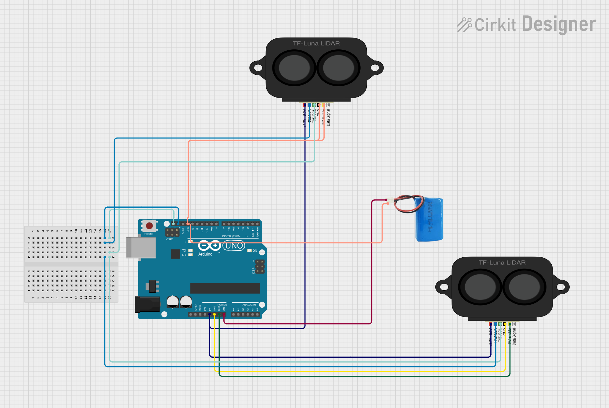

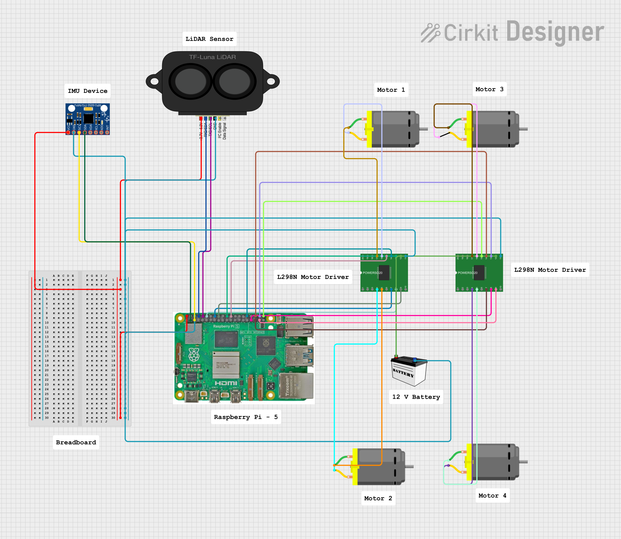
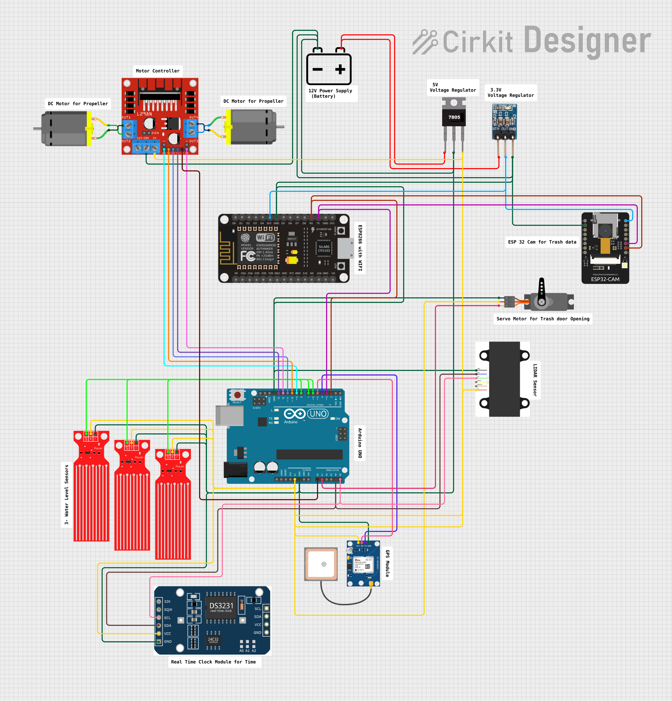
Explore Projects Built with 3D LIDAR
Common Applications and Use Cases
- Autonomous Vehicles: For obstacle detection and navigation.
- Robotics: For spatial mapping and object recognition.
- Mapping: For creating detailed topographic maps.
- Environmental Monitoring: For studying terrain and vegetation.
Technical Specifications
The following table outlines the key technical specifications of the Raspberry PI 3D LIDAR sensor:
| Specification | Detail |
|---|---|
| Operating Voltage | 5V DC |
| Power Consumption | 3.5W (typical) |
| Measurement Range | 0.1 to 40 meters |
| Angular Resolution | 0.1 to 0.4 degrees |
| Field of View | 360 degrees horizontally, 30 degrees vertically |
| Interface | I2C, UART, Ethernet |
| Operating Temperature | -10°C to +50°C |
| Laser Class | Class 1 (eye-safe) |
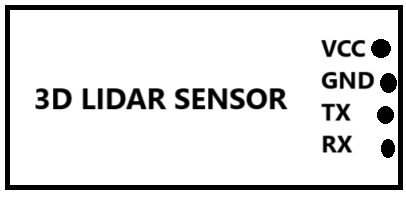
Pin Configuration and Descriptions
| Pin Number | Name | Description |
|---|---|---|
| 1 | VCC | Power supply (5V DC) |
| 2 | GND | Ground |
| 3 | SDA | I2C Data Line |
| 4 | SCL | I2C Clock Line |
| 5 | TX | UART Transmit |
| 6 | RX | UART Receive |
| 7 | ETH | Ethernet connection for high-speed data transfer |
Usage Instructions
Integrating with a Circuit
- Power Supply: Connect the VCC pin to a 5V power source and the GND pin to the common ground.
- Data Communication: Choose between I2C or UART for communication with a microcontroller or computer. For I2C, connect SDA and SCL to the corresponding pins on the microcontroller. For UART, connect the TX and RX pins.
- Ethernet: For applications requiring high-speed data transfer, use an Ethernet cable to connect the ETH pin to a network.
Important Considerations and Best Practices
- Ensure that the power supply is stable and within the specified voltage range to prevent damage.
- When handling the sensor, take precautions to avoid electrostatic discharge (ESD) which can damage the electronics.
- For accurate measurements, the sensor should be mounted on a stable platform, free from vibrations and excessive movement.
- Regularly clean the sensor's optical components with a soft, dry cloth to ensure optimal performance.
Troubleshooting and FAQs
Common Issues
- Inaccurate Measurements: Ensure that the sensor is not obstructed and that the optical components are clean. Check for software calibration issues.
- No Data Output: Verify that the power supply is correctly connected and within the specified range. Check the data communication connections and configurations.
Solutions and Tips for Troubleshooting
- Power Cycle: If the sensor is unresponsive, try power cycling the device.
- Connection Check: Double-check all connections, including power and data lines, for any loose wires or incorrect wiring.
- Software Configuration: Ensure that the software settings, such as baud rate for UART or I2C address, match the sensor's specifications.
FAQs
Q: What is the maximum range of the sensor? A: The sensor can measure distances from 0.1 to 40 meters.
Q: Is the laser safe for eyes? A: Yes, the sensor uses a Class 1 laser which is considered eye-safe.
Q: Can the sensor be used outdoors? A: The sensor is designed to operate within a temperature range of -10°C to +50°C. However, performance can be affected by weather conditions such as rain or fog.
Q: How can I interface the sensor with an Arduino UNO? A: You can use the I2C or UART interface to connect the sensor to an Arduino UNO. Ensure you have the appropriate libraries and configure the microcontroller to communicate with the sensor.
Example Code for Arduino UNO
Below is an example of how to interface the 3D LIDAR sensor with an Arduino UNO using the I2C communication protocol. This code is for demonstration purposes and may require additional libraries or adjustments based on the specific sensor model and manufacturer's specifications.
#include <Wire.h>

// Define the I2C address of the LIDAR sensor (replace with actual address)
#define LIDAR_ADDR 0x62

void setup() {
  Wire.begin(); // Initialize I2C
  Serial.begin(9600); // Start serial communication at 9600 baud
}

void loop() {
  // Send a measurement command to the LIDAR sensor
  Wire.beginTransmission(LIDAR_ADDR);
  Wire.write(0x00); // Command register address
  Wire.write(0x04); // Command to initiate measurement
  Wire.endTransmission();

  // Wait for the measurement to complete
  delay(50);

  // Request 2 bytes from the sensor (distance data)
  Wire.requestFrom(LIDAR_ADDR, 2);
  if (Wire.available() >= 2) {
    int distance = Wire.read() << 8; // High byte
    distance |= Wire.read(); // Low byte

    // Print the distance to the Serial Monitor
    Serial.print("Distance: ");
    Serial.print(distance);
    Serial.println(" cm");
  }

  // Wait before taking the next measurement
  delay(1000);
}
Remember to consult the sensor's datasheet and the manufacturer's resources for specific commands and data formats required for communication and control of the 3D LIDAR sensor.