How to Use I2S MEMS Microphone: Examples, Pinouts, and Specs
Introduction
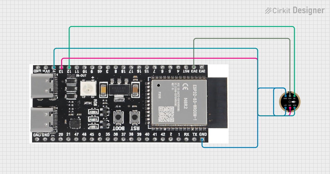
The Fermion I2S MEMS Microphone (Part ID: SEN0526) is a compact, high-performance digital microphone designed for audio data transmission using the I2S (Inter-IC Sound) protocol. Built with Micro-Electro-Mechanical System (MEMS) technology, this microphone offers excellent sound quality in a small form factor, making it ideal for applications where space is limited.
Explore Projects Built with I2S MEMS Microphone
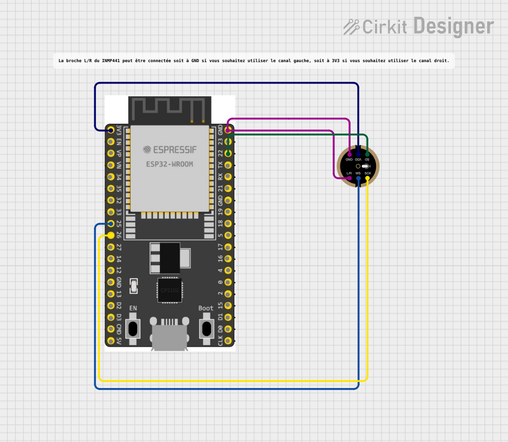
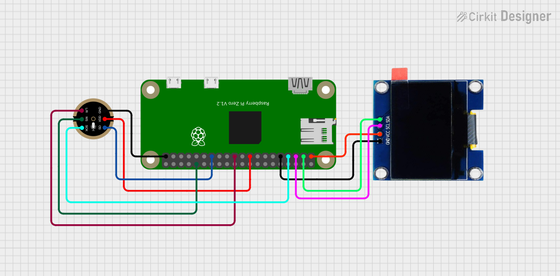
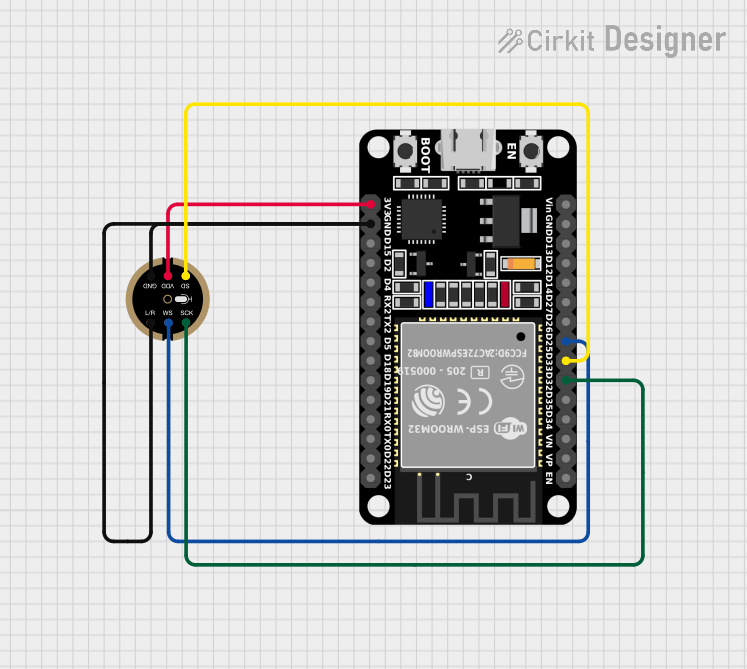
Explore Projects Built with I2S MEMS Microphone
Common Applications and Use Cases
- Voice recognition systems
- Audio recording devices
- Smart home assistants
- IoT devices with audio input
- Noise monitoring and analysis systems
Technical Specifications
The following table outlines the key technical details of the Fermion I2S MEMS Microphone:
| Parameter | Value |
|---|---|
| Operating Voltage | 1.8V to 3.6V |
| Current Consumption | 0.8 mA (typical) |
| Signal-to-Noise Ratio | 64 dB |
| Frequency Response | 50 Hz to 20 kHz |
| Sensitivity | -26 dBFS ±3 dB |
| Output Format | I2S (Inter-IC Sound) |
| Dimensions | 15 mm x 10 mm x 1.5 mm |
| Operating Temperature | -40°C to +85°C |
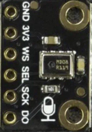
Pin Configuration and Descriptions
The Fermion I2S MEMS Microphone has a simple pinout, as described in the table below:
| Pin Name | Pin Type | Description |
|---|---|---|
| VDD | Power | Power supply pin (1.8V to 3.6V). |
| GND | Ground | Ground connection. |
| WS | Input | Word Select pin for I2S protocol. |
| SCK | Input | Serial Clock pin for I2S protocol. |
| SD | Output | Serial Data output pin for I2S protocol. |
Usage Instructions
How to Use the Component in a Circuit
- Power Supply: Connect the VDD pin to a stable power source (1.8V to 3.6V) and the GND pin to ground.
- I2S Connections:
- Connect the WS pin to the Word Select line of your I2S master device.
- Connect the SCK pin to the Serial Clock line of your I2S master device.
- Connect the SD pin to the Serial Data input of your I2S master device.
- Pull-Up Resistors: Ensure proper pull-up resistors are used on the I2S lines if required by your system.
- Microphone Placement: Place the microphone in a location free from obstructions to ensure optimal sound capture.
Important Considerations and Best Practices
- Power Supply Noise: Use a decoupling capacitor (e.g., 0.1 µF) close to the VDD pin to minimize power supply noise.
- Clock Configuration: Ensure the I2S master device provides a clock signal compatible with the microphone's specifications.
- Orientation: Position the microphone so that the sound source is directed toward the sound port for best performance.
- ESD Protection: Handle the microphone carefully to avoid electrostatic discharge damage.
Example: Connecting to an Arduino UNO
The Fermion I2S MEMS Microphone can be interfaced with an Arduino UNO using an I2S-compatible breakout board or shield. Below is an example Arduino sketch to read audio data:
#include <I2S.h> // Include the I2S library for Arduino

void setup() {
  Serial.begin(9600); // Initialize serial communication for debugging

  // Initialize I2S in receive mode
  if (!I2S.begin(I2S_PHILIPS_MODE, 44100)) {
    Serial.println("Failed to initialize I2S!");
    while (1); // Halt execution if I2S initialization fails
  }

  Serial.println("I2S MEMS Microphone Initialized");
}

void loop() {
  int sample = 0;

  // Check if audio data is available
  if (I2S.available()) {
    sample = I2S.read(); // Read audio sample from the microphone

    // Print the audio sample to the Serial Monitor
    Serial.println(sample);
  }
}
Notes:
- The above code assumes a sampling rate of 44.1 kHz. Adjust the sampling rate as needed for your application.
- Ensure the I2S pins on the Arduino are correctly connected to the microphone's pins.
Troubleshooting and FAQs
Common Issues and Solutions
No Audio Data Output:
- Verify that the I2S clock signals (SCK and WS) are being generated by the master device.
- Check the connections between the microphone and the I2S master device.
- Ensure the microphone is powered correctly (1.8V to 3.6V).
Distorted Audio:
- Ensure the microphone is not placed too close to a loud sound source.
- Verify that the sampling rate matches the microphone's specifications.
High Noise Levels:
- Use a decoupling capacitor near the VDD pin to reduce power supply noise.
- Ensure the microphone is not exposed to excessive electromagnetic interference.
FAQs
Q: Can I use this microphone with a Raspberry Pi?
A: Yes, the Fermion I2S MEMS Microphone is compatible with Raspberry Pi devices that support I2S communication. Ensure the I2S pins are correctly configured in the Raspberry Pi's software.
Q: What is the maximum distance between the microphone and the I2S master device?
A: The maximum distance depends on the quality of the connections and the environment. For best results, keep the distance as short as possible to minimize signal degradation.
Q: Can this microphone capture stereo audio?
A: No, the Fermion I2S MEMS Microphone is a mono microphone. For stereo audio, you would need two microphones and an appropriate I2S configuration.
Q: Is this microphone suitable for outdoor use?
A: The microphone operates in a wide temperature range (-40°C to +85°C), but it is not waterproof. Additional protection is required for outdoor use.