How to Use Arduino Nano RP 2040 connect: Examples, Pinouts, and Specs
Introduction
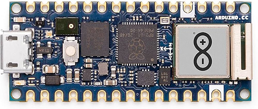
The Arduino Nano RP2040 Connect is a compact microcontroller board powered by the RP2040 chip, developed by Raspberry Pi. It is designed for seamless integration with a wide range of sensors and modules, making it ideal for IoT (Internet of Things) applications. This board stands out due to its built-in Wi-Fi and Bluetooth capabilities, enabling wireless communication for smart devices and connected systems.
Explore Projects Built with Arduino Nano RP 2040 connect
Explore Projects Built with Arduino Nano RP 2040 connect
Common Applications and Use Cases
- IoT devices and smart home automation
- Wireless sensor networks
- Robotics and automation systems
- Data logging and remote monitoring
- Prototyping and educational projects
Technical Specifications
The Arduino Nano RP2040 Connect combines the power of the RP2040 microcontroller with additional features for wireless communication and enhanced functionality.
Key Technical Details
| Specification | Value |
|---|---|
| Microcontroller | RP2040 (Dual-core ARM Cortex-M0+) |
| Clock Speed | 133 MHz |
| Flash Memory | 16 MB |
| SRAM | 264 KB |
| Wireless Connectivity | Wi-Fi (802.11 b/g/n) and Bluetooth 4.2 |
| Operating Voltage | 3.3V |
| Input Voltage (VIN) | 5V |
| Digital I/O Pins | 20 |
| PWM Pins | 20 |
| Analog Input Pins | 8 |
| Communication Interfaces | UART, I2C, SPI |
| USB Interface | Micro USB |
| Dimensions | 45 x 18 mm |
Pin Configuration and Descriptions
The Arduino Nano RP2040 Connect has a total of 28 pins, including power, digital, and analog pins. Below is the pinout description:
| Pin Number | Pin Name | Description |
|---|---|---|
| 1 | VIN | Input voltage (5V) for powering the board |
| 2 | GND | Ground |
| 3 | 3.3V | 3.3V output for powering external devices |
| 4-11 | D0-D7 | Digital I/O pins |
| 12-19 | D8-D13, A0-A3 | Digital I/O and Analog Input pins |
| 20 | A4 (SDA) | I2C Data Line |
| 21 | A5 (SCL) | I2C Clock Line |
| 22 | RX | UART Receive |
| 23 | TX | UART Transmit |
| 24 | SPI SCK | SPI Clock |
| 25 | SPI MISO | SPI Master In Slave Out |
| 26 | SPI MOSI | SPI Master Out Slave In |
| 27 | RESET | Reset the board |
| 28 | Wi-Fi/BLE Ant. | Internal antenna for wireless communication |
Usage Instructions
The Arduino Nano RP2040 Connect is versatile and easy to use. Below are the steps to get started and best practices for using the board effectively.
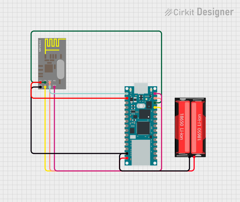
How to Use the Component in a Circuit
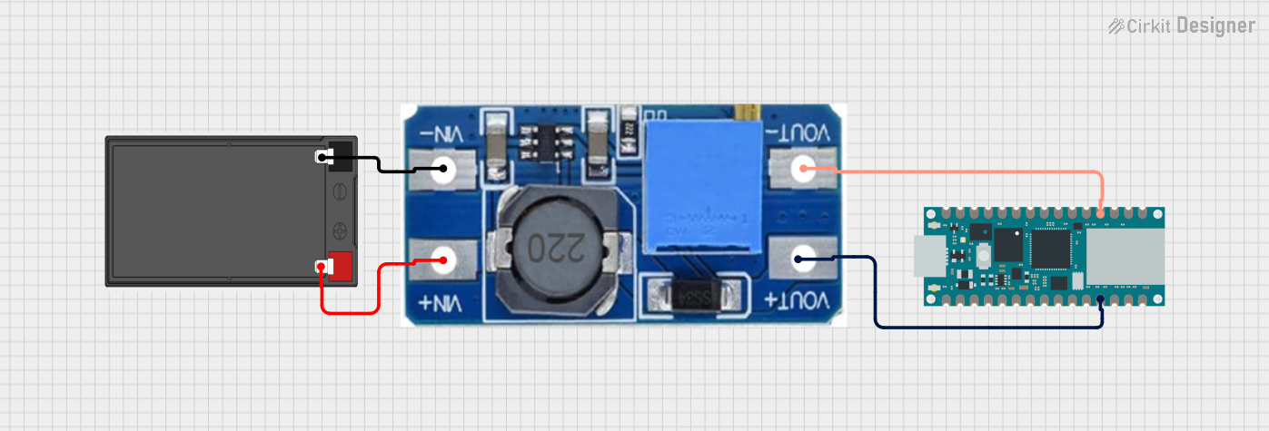
Powering the Board:
- Use the VIN pin (5V) or the Micro USB port to power the board.
- Ensure the power supply is stable and within the recommended voltage range.
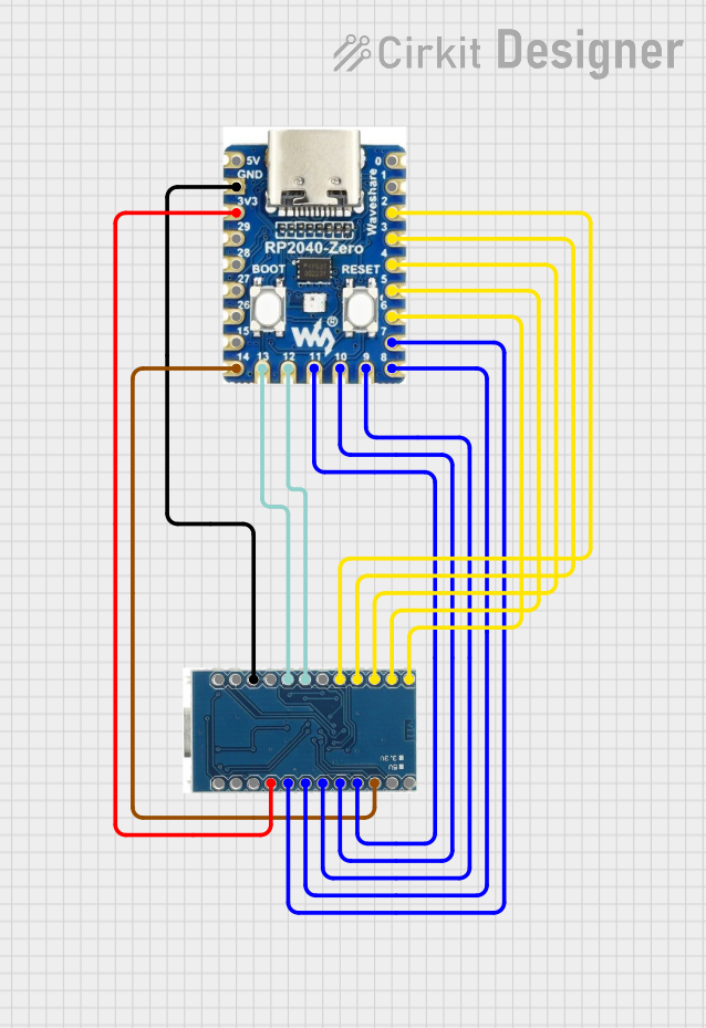
Connecting Sensors and Modules:
- Use the digital and analog pins to connect sensors and actuators.
- For I2C devices, connect to the SDA (A4) and SCL (A5) pins.
- For SPI devices, use the SPI SCK, MISO, and MOSI pins.
Programming the Board:
- Install the Arduino IDE and add the "Arduino Mbed OS RP2040" board package.
- Connect the board to your computer via the Micro USB cable.
- Select the correct board and port in the Arduino IDE, then upload your code.
Important Considerations and Best Practices
- Voltage Levels: The board operates at 3.3V logic levels. Avoid connecting 5V signals directly to the pins. Use a level shifter if necessary.
- Wi-Fi and Bluetooth: Ensure a stable power supply when using wireless features to avoid connection drops.
- Heat Management: While the board is efficient, prolonged use of Wi-Fi or Bluetooth may generate heat. Ensure proper ventilation.
- Firmware Updates: Regularly check for firmware updates for the wireless module to ensure optimal performance.
Example Code for Arduino Nano RP2040 Connect
Below is an example code to connect the board to a Wi-Fi network and print the IP address:
#include <WiFiNINA.h> // Include the Wi-Fi library

// Replace with your network credentials
const char* ssid = "Your_SSID";
const char* password = "Your_PASSWORD";

void setup() {
  Serial.begin(9600); // Start serial communication
  while (!Serial);    // Wait for the serial monitor to open

  Serial.println("Connecting to Wi-Fi...");
  WiFi.begin(ssid, password); // Connect to Wi-Fi

  while (WiFi.status() != WL_CONNECTED) {
    delay(1000); // Wait for connection
    Serial.print(".");
  }

  Serial.println("\nConnected to Wi-Fi!");
  Serial.print("IP Address: ");
  Serial.println(WiFi.localIP()); // Print the IP address
}

void loop() {
  // Add your main code here
}
Troubleshooting and FAQs
Common Issues Users Might Face
Board Not Detected by the Arduino IDE:
- Ensure the correct board package is installed in the Arduino IDE.
- Check the USB cable and port for proper connection.
- Try pressing the RESET button on the board.
Wi-Fi Connection Fails:
- Double-check the SSID and password.
- Ensure the Wi-Fi network is within range.
- Update the Wi-Fi firmware using the Arduino IDE.
Code Upload Fails:
- Verify the correct COM port is selected in the Arduino IDE.
- Ensure no other application is using the COM port.
- Press and hold the BOOTSEL button while connecting the board to enter bootloader mode.
Solutions and Tips for Troubleshooting
- Debugging with Serial Monitor: Use
Serial.print()statements to debug your code and monitor the board's behavior. - Firmware Updates: Use the "WiFiNINA Firmware Updater" tool in the Arduino IDE to update the wireless module firmware.
- Resetting the Board: If the board becomes unresponsive, press the RESET button or re-flash the firmware.
By following this documentation, you can effectively use the Arduino Nano RP2040 Connect for a wide range of projects and applications.