How to Use step up: Examples, Pinouts, and Specs
Introduction
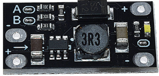
A step-up converter, also known as a boost converter, is a DC-DC converter designed to increase the input voltage to a higher output voltage while maintaining power balance. Manufactured by Arduino with the part ID "UNO," this component is widely used in applications requiring voltage amplification. It is an essential tool in battery-powered devices, renewable energy systems, and portable electronics where higher voltage levels are needed.
Explore Projects Built with step up


Explore Projects Built with step up
Common Applications and Use Cases
- Powering high-voltage devices from low-voltage batteries
- Solar power systems to step up panel voltage
- LED drivers for high-brightness LEDs
- Portable electronics requiring efficient voltage conversion
- Robotics and IoT devices powered by low-voltage sources
Technical Specifications
The Arduino Step-Up Converter (UNO) is designed for efficient voltage boosting with the following specifications:
| Parameter | Value |
|---|---|
| Input Voltage Range | 2V to 24V |
| Output Voltage Range | 5V to 48V |
| Maximum Output Current | 2A (depends on input voltage) |
| Efficiency | Up to 95% |
| Switching Frequency | 150 kHz |
| Operating Temperature | -40°C to +85°C |
| Dimensions | 25mm x 20mm x 10mm |
Pin Configuration and Descriptions
The step-up converter has the following pin configuration:
| Pin Name | Description |
|---|---|
| VIN | Input voltage pin. Connect to the DC power source. |
| GND | Ground pin. Connect to the ground of the circuit. |
| VOUT | Output voltage pin. Provides the boosted voltage. |
| EN (Enable) | Enable pin. High to enable the converter, low to disable. |
Usage Instructions
How to Use the Component in a Circuit
Connect the Input Voltage (VIN):
Attach the positive terminal of your DC power source to the VIN pin and the negative terminal to the GND pin.Connect the Output Load:
Connect the device or circuit requiring the boosted voltage to the VOUT pin and GND pin.Enable the Converter:
If the EN pin is available, ensure it is connected to a HIGH signal (e.g., 5V) to enable the converter. If left floating, the converter may not operate.Adjust Output Voltage (if applicable):
Some step-up converters include a potentiometer to adjust the output voltage. Turn the potentiometer clockwise or counterclockwise to set the desired output voltage.
Important Considerations and Best Practices
- Input Voltage Range: Ensure the input voltage is within the specified range (2V to 24V). Exceeding this range may damage the converter.
- Output Current Limit: Do not exceed the maximum output current (2A). Overloading the converter can cause overheating or failure.
- Heat Dissipation: For high-power applications, ensure proper heat dissipation using heatsinks or active cooling.
- Ripple and Noise: Use appropriate capacitors at the input and output to minimize voltage ripple and noise.
- Polarity Protection: Double-check the polarity of the input and output connections to avoid damage.
Example: Using the Step-Up Converter with Arduino UNO
Below is an example of connecting the step-up converter to an Arduino UNO to power a 12V motor from a 5V source.
Circuit Connections
- Connect the 5V output of the Arduino UNO to the VIN pin of the step-up converter.
- Connect the GND pin of the Arduino UNO to the GND pin of the step-up converter.
- Connect the VOUT pin of the step-up converter to the positive terminal of the motor.
- Connect the negative terminal of the motor to the GND pin of the step-up converter.
Arduino Code Example
// Example code to control a 12V motor using a step-up converter and Arduino UNO

const int motorPin = 9; // PWM pin connected to motor control circuit

void setup() {
  pinMode(motorPin, OUTPUT); // Set motor pin as output
}

void loop() {
  analogWrite(motorPin, 128); // Set motor speed to 50% (PWM value: 128)
  delay(5000);               // Run motor for 5 seconds

  analogWrite(motorPin, 0);  // Stop motor
  delay(2000);               // Wait for 2 seconds before restarting
}
Troubleshooting and FAQs
Common Issues and Solutions
No Output Voltage:
- Cause: EN pin is not connected or set to LOW.
- Solution: Connect the EN pin to a HIGH signal (e.g., 5V) to enable the converter.
Overheating:
- Cause: Exceeding the maximum output current or insufficient cooling.
- Solution: Reduce the load current or add a heatsink to the converter.
High Voltage Ripple:
- Cause: Insufficient input/output capacitors.
- Solution: Add low-ESR capacitors (e.g., 100µF) at the input and output.
Output Voltage Not Stable:
- Cause: Input voltage is too low or fluctuating.
- Solution: Ensure the input voltage is within the specified range and stable.
FAQs
Q: Can I use the step-up converter to power an Arduino UNO?
A: Yes, you can use the step-up converter to provide a stable 5V or 9V output to power the Arduino UNO via its VIN or 5V pin.
Q: How do I calculate the input current required for my load?
A: Use the formula:
[
I_{in} = \frac{V_{out} \times I_{out}}{V_{in} \times \text{Efficiency}}
]
For example, if your load requires 12V at 1A, and the input voltage is 5V with 90% efficiency:
[
I_{in} = \frac{12 \times 1}{5 \times 0.9} = 2.67A
]
Q: Can I use this converter with a solar panel?
A: Yes, the step-up converter is suitable for solar panels. Ensure the panel's output voltage and current are within the converter's input range and power limits.