How to Use Cytron MDD3A Motor Driver: Examples, Pinouts, and Specs
Introduction
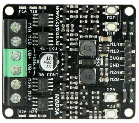
The Cytron MDD3A Motor Driver is a dual-channel motor driver designed to control two DC motors with adjustable speed and direction. It is compact, efficient, and easy to use, making it ideal for robotics, automation, and other motor control applications. The MDD3A supports both PWM (Pulse Width Modulation) and direction control, allowing precise motor operation. Its robust design ensures reliable performance in a wide range of projects.
Explore Projects Built with Cytron MDD3A Motor Driver


Explore Projects Built with Cytron MDD3A Motor Driver
Common Applications
- Robotics (e.g., mobile robots, robotic arms)
- Conveyor belt systems
- Automated guided vehicles (AGVs)
- DIY motorized projects
- Educational and prototyping purposes
Technical Specifications
Below are the key technical details of the Cytron MDD3A Motor Driver:
| Parameter | Specification |
|---|---|
| Operating Voltage | 5V to 30V DC |
| Continuous Current (per channel) | 3A |
| Peak Current (per channel) | 5A |
| Control Interface | PWM and Direction |
| PWM Frequency Range | Up to 20 kHz |
| Logic Voltage | 3.3V or 5V compatible |
| Dimensions | 37mm x 37mm x 15mm |
| Weight | 15g |
Pin Configuration and Descriptions
The Cytron MDD3A has a total of 8 pins. The table below describes each pin:
| Pin Name | Type | Description |
|---|---|---|
| VM | Power Input | Motor power supply (5V to 30V DC). Connect to the positive terminal of the power source. |
| GND | Power Ground | Ground connection for the motor power supply. |
| VCC | Logic Input | Logic voltage input (3.3V or 5V). |
| GND | Logic Ground | Ground connection for the logic circuit. |
| AIN1 | Input | Control signal for Motor A direction. |
| AIN2 | Input | Control signal for Motor A speed (PWM). |
| BIN1 | Input | Control signal for Motor B direction. |
| BIN2 | Input | Control signal for Motor B speed (PWM). |
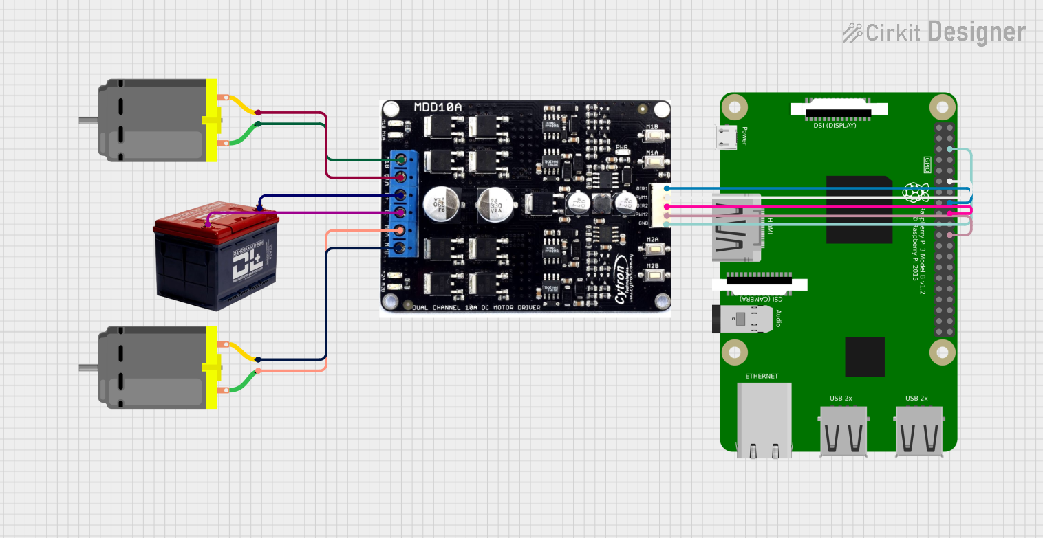
Usage Instructions
Connecting the Cytron MDD3A
- Power Supply: Connect the motor power supply (5V to 30V DC) to the
VMpin and the ground to theGNDpin. - Logic Voltage: Connect the logic voltage (3.3V or 5V) to the
VCCpin and the ground to theGNDpin. - Motor Connections:
- Connect the terminals of Motor A to the motor output pins labeled
Motor A. - Connect the terminals of Motor B to the motor output pins labeled
Motor B.
- Connect the terminals of Motor A to the motor output pins labeled
- Control Signals:
- Use the
AIN1andAIN2pins to control the direction and speed of Motor A. - Use the
BIN1andBIN2pins to control the direction and speed of Motor B.
- Use the
Example Arduino UNO Code
Below is an example of how to control two DC motors using the Cytron MDD3A with an Arduino UNO:
// Define motor control pins
const int AIN1 = 3; // Motor A direction control
const int AIN2 = 5; // Motor A speed control (PWM)
const int BIN1 = 6; // Motor B direction control
const int BIN2 = 9; // Motor B speed control (PWM)

void setup() {
  // Set motor control pins as outputs
  pinMode(AIN1, OUTPUT);
  pinMode(AIN2, OUTPUT);
  pinMode(BIN1, OUTPUT);
  pinMode(BIN2, OUTPUT);
}

void loop() {
  // Example: Rotate Motor A forward at 50% speed
  digitalWrite(AIN1, HIGH); // Set direction forward
  analogWrite(AIN2, 128);   // Set speed (128 = 50% of 255)

  // Example: Rotate Motor B backward at 75% speed
  digitalWrite(BIN1, LOW);  // Set direction backward
  analogWrite(BIN2, 192);   // Set speed (192 = 75% of 255)

  delay(2000); // Run motors for 2 seconds

  // Stop both motors
  analogWrite(AIN2, 0);     // Stop Motor A
  analogWrite(BIN2, 0);     // Stop Motor B

  delay(2000); // Wait for 2 seconds before repeating
}
Important Considerations
- Ensure the motor power supply voltage is within the specified range (5V to 30V DC).
- Do not exceed the continuous current rating of 3A per channel to avoid overheating or damage.
- Use appropriate heat dissipation methods (e.g., heat sinks) if operating near the peak current limit.
- Verify that the logic voltage matches the microcontroller's output voltage (3.3V or 5V).
Troubleshooting and FAQs
Common Issues and Solutions
Motors not running:
- Check the power supply connections to the
VMandGNDpins. - Verify that the control signals (
AIN1,AIN2,BIN1,BIN2) are correctly configured. - Ensure the motor power supply voltage is within the specified range.
- Check the power supply connections to the
Motor runs in the wrong direction:
- Reverse the logic level of the direction control pins (
AIN1orBIN1). - Swap the motor terminals connected to the motor output pins.
- Reverse the logic level of the direction control pins (
Overheating:
- Ensure the current drawn by the motors does not exceed 3A per channel.
- Add a heat sink or improve ventilation around the motor driver.
PWM signal not working:
- Verify that the PWM frequency is within the supported range (up to 20 kHz).
- Check the microcontroller's PWM pin configuration and ensure it is functioning correctly.
FAQs
Q: Can I use the Cytron MDD3A with a 3.3V microcontroller?
A: Yes, the MDD3A is compatible with both 3.3V and 5V logic levels. Connect the VCC pin to the appropriate logic voltage.
Q: What happens if the motor draws more than 3A continuously?
A: Exceeding the continuous current rating may cause the motor driver to overheat or fail. Use motors within the specified current limits.
Q: Can I control only one motor with the MDD3A?
A: Yes, you can use only one channel (Motor A or Motor B) if your application requires controlling a single motor.
Q: Is the MDD3A suitable for stepper motors?
A: No, the MDD3A is designed for DC motors and is not suitable for stepper motor control.
By following this documentation, you can effectively integrate the Cytron MDD3A Motor Driver into your projects for reliable motor control.