How to Use ESP32 (30 pin): Examples, Pinouts, and Specs
Introduction
The ESP32 is a powerful and versatile microcontroller designed for IoT (Internet of Things) applications and embedded systems. It features built-in Wi-Fi and Bluetooth capabilities, making it an excellent choice for wireless communication projects. With its 30-pin configuration, the ESP32 offers a wide range of GPIO (General Purpose Input/Output) pins, ADC (Analog-to-Digital Converter) channels, PWM (Pulse Width Modulation) outputs, and other peripherals, enabling developers to create complex and efficient systems.
Explore Projects Built with ESP32 (30 pin)


Explore Projects Built with ESP32 (30 pin)
Common Applications and Use Cases
- IoT devices and smart home automation
- Wireless sensor networks
- Wearable technology
- Robotics and drones
- Data logging and remote monitoring
- Industrial automation
Technical Specifications
Key Technical Details
| Specification | Value |
|---|---|
| Microcontroller | Tensilica Xtensa LX6 dual-core processor |
| Clock Speed | Up to 240 MHz |
| Flash Memory | 4 MB (varies by model) |
| SRAM | 520 KB |
| Wi-Fi Standard | 802.11 b/g/n |
| Bluetooth Version | Bluetooth 4.2 + BLE |
| Operating Voltage | 3.3V |
| Input Voltage Range | 5V (via USB) or 3.3V (via VIN pin) |
| GPIO Pins | 30 |
| ADC Channels | 18 (12-bit resolution) |
| PWM Outputs | Multiple (configurable on GPIO pins) |
| Communication Interfaces | UART, SPI, I2C, I2S, CAN, Ethernet |
| Power Consumption | Ultra-low power (varies by mode) |
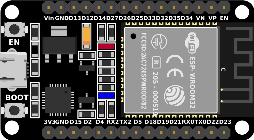
Pin Configuration and Descriptions
The ESP32 (30-pin variant) has the following pinout:
| Pin Number | Pin Name | Description |
|---|---|---|
| 1 | EN | Enable pin (active high) |
| 2 | IO1 | GPIO1, UART TXD |
| 3 | IO3 | GPIO3, UART RXD |
| 4 | IO4 | GPIO4, ADC2_CH0, Touch 0 |
| 5 | IO5 | GPIO5, ADC2_CH1, Touch 1 |
| 6 | GND | Ground |
| 7 | IO6 | GPIO6, SPI Flash SCK |
| 8 | IO7 | GPIO7, SPI Flash SD0 |
| 9 | IO8 | GPIO8, SPI Flash SD1 |
| 10 | IO9 | GPIO9, SPI Flash SD2 |
| 11 | IO10 | GPIO10, SPI Flash SD3 |
| 12 | IO12 | GPIO12, ADC2_CH5, Touch 2 |
| 13 | IO13 | GPIO13, ADC2_CH4, Touch 3 |
| 14 | IO14 | GPIO14, ADC2_CH6, Touch 4 |
| 15 | IO15 | GPIO15, ADC2_CH3, Touch 5 |
| 16 | IO16 | GPIO16, ADC2_CH2, Touch 6 |
| 17 | IO17 | GPIO17, ADC2_CH7, Touch 7 |
| 18 | IO18 | GPIO18, SPI CLK |
| 19 | IO19 | GPIO19, SPI MISO |
| 20 | IO21 | GPIO21, I2C SDA |
| 21 | IO22 | GPIO22, I2C SCL |
| 22 | IO23 | GPIO23, SPI MOSI |
| 23 | IO25 | GPIO25, ADC2_CH8, DAC1 |
| 24 | IO26 | GPIO26, ADC2_CH9, DAC2 |
| 25 | IO27 | GPIO27, ADC2_CH10 |
| 26 | IO32 | GPIO32, ADC1_CH4, Touch 9 |
| 27 | IO33 | GPIO33, ADC1_CH5, Touch 8 |
| 28 | IO34 | GPIO34, ADC1_CH6 |
| 29 | IO35 | GPIO35, ADC1_CH7 |
| 30 | VIN | Power input (5V) |
Usage Instructions
How to Use the ESP32 in a Circuit
Powering the ESP32:
- Use a 5V power source via the VIN pin or connect it to a USB port.
- Ensure the power supply is stable to avoid unexpected resets.
Connecting Peripherals:
- Use GPIO pins for digital input/output.
- For analog input, connect sensors to ADC pins (e.g., IO32, IO33).
- For communication, use UART, SPI, or I2C pins as needed.
Programming the ESP32:
- Install the ESP32 board package in the Arduino IDE or use the ESP-IDF framework.
- Connect the ESP32 to your computer via USB and select the correct COM port.
- Write and upload your code to the ESP32.
Important Considerations and Best Practices
- Voltage Levels: The ESP32 operates at 3.3V logic levels. Avoid connecting 5V signals directly to GPIO pins.
- Boot Mode: Ensure the IO0 pin is pulled low during boot to enter programming mode.
- Power Consumption: Use deep sleep mode to reduce power consumption in battery-powered applications.
- Wi-Fi Interference: Avoid placing the ESP32 near metal objects or other devices that may interfere with its Wi-Fi signal.
Example Code for Arduino UNO Integration
The following example demonstrates how to connect the ESP32 to a Wi-Fi network and send data to a server:
#include <WiFi.h> // Include the WiFi library for ESP32

// Replace with your network credentials
const char* ssid = "Your_SSID";
const char* password = "Your_PASSWORD";

void setup() {
  Serial.begin(115200); // Initialize serial communication
  delay(1000); // Wait for serial monitor to initialize

  Serial.println("Connecting to Wi-Fi...");
  WiFi.begin(ssid, password); // Connect to Wi-Fi

  while (WiFi.status() != WL_CONNECTED) {
    delay(500); // Wait for connection
    Serial.print(".");
  }

  Serial.println("\nWi-Fi connected!");
  Serial.print("IP Address: ");
  Serial.println(WiFi.localIP()); // Print the ESP32's IP address
}

void loop() {
  // Add your main code here
}
Troubleshooting and FAQs
Common Issues and Solutions
ESP32 Not Connecting to Wi-Fi:
- Double-check the SSID and password.
- Ensure the router is within range and supports 2.4 GHz Wi-Fi (ESP32 does not support 5 GHz).
Upload Fails in Arduino IDE:
- Ensure the correct board and COM port are selected.
- Hold the BOOT button on the ESP32 while uploading the code.
Random Resets or Instability:
- Verify the power supply is stable and capable of providing sufficient current (at least 500 mA).
- Avoid using long or thin wires for power connections.
GPIO Pin Not Working:
- Check if the pin is being used for another function (e.g., ADC, Touch).
- Ensure the pin is not damaged or shorted.
FAQs
Q: Can the ESP32 be powered directly from a 5V source?
A: Yes, the ESP32 can be powered via the VIN pin with a 5V source. However, the GPIO pins operate at 3.3V logic levels.
Q: How do I reset the ESP32?
A: Press the EN (Enable) button to reset the ESP32.
Q: Can I use the ESP32 with a 5V sensor?
A: Use a voltage divider or level shifter to step down the 5V signal to 3.3V before connecting it to the ESP32 GPIO pins.